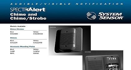
System Sensor SAA Chimes Chime Strobes

File Preview
Click below to download for free
Click below to download for free
File Data
| Name | system-sensor-saa-chimes-chime-strobes-9213680745.pdf |
|---|---|
| Type | |
| Size | 957.66 KB |
| Downloads |
Text Preview
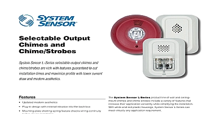
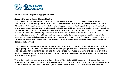
Selectable Output and Chime Advance selectable output chimes and chime are rich with features guaranteed to cut installation and maximize profits Plug in design with minimal intrusion into the back box Mounting plate shorting spring feature checks wiring continuity device installation Captive mounting screw Tamper resistant construction Field selectable candela settings 15 15 75 30 75 95 110 115 Automatic selection of 12 or 24 volt operation at 15 and candela Five selectable tones Rotary switch for tone selection and volume selections Electrically compatible with legacy SpectrAlert devices Listed for ceiling or wall mounting the entire SpectrAlert Advance product line wall mount and chime strobes include a variety of features that increase application versatility while simplifying the installation With and red plastic housings wall and ceiling mounting options Advance can meet virtually any application requirement chimes and chime strobes are private mode appliances used to alert trained personnel to investigate emergency situations and to take appropriate action guard and nurse workstations are ideal locations for products devices feature plug in design with minimal intrusion into the box making the installation fast and foolproof while virtually costly and time consuming ground faults can easily adapt devices to a wide range of application using field selectable candela settings automatic of 12 or 24 volt operation and a rotary switch for chime and two volume selections Listings chime strobes chimes Advance Specifications Specifications Advance chimes and chime strobes shall mount to a standard 4 4 1 back box 4 inch octagon back box single gang 4 17 8 inch back box or double gang back box A universal mounting plate shall be used for mounting products The notification circuit wiring shall terminate at the universal mounting plate Also SpectrAlert Advance products when used with the Sync accessory shall be powered from a non coded notification appliance circuit output and shall operate on a nominal 12 or 24 volts used with the Sync Module 12 volt rated notification appliance circuit outputs shall operate between 8.5 and 17.5 volts 24 rated notification appliance circuit outputs shall operate between 16.5 and 33 volts Indoor SpectrAlert Advance products shall operate 32 and 120 degrees Fahrenheit from a regulated DC or full wave rectified unfiltered power supply Chime strobes shall have field candela settings of 15 15 75 30 75 95 110 and 115 Combination chime strobe shall be a System Sensor SpectrAlert Advance Model listed to UL 1638 and UL 464 The chime strobe shall comply the Americans with Disabilities Act requirements for visible signaling appliances flashing at 1Hz over the strobe entire operating voltage The strobe light shall consist of a xenon flash tube and associated lens reflector system The chime shall have two audibility options an option to switch between temporal three pattern non temporal continuous pattern 1 second chime pattern 1 4 second chime 5 second whoop chime pattern These options are set by a multiple position switch Module module shall be a System Sensor Sync listed to UL 464 and shall be approved for fire protective service The module shall SpectrAlert strobes at 1Hz and all available chime tones Also while operating the strobes the module shall silence the chimes chime strobe models over a single pair of wires The module shall mount to a 4 11 16 4 11 16 2 1 8 inch back box The module shall control two Style Y class B circuits or one Style Z class A circuit The module shall synchronize multiple zones Daisy chaining two or synchronization modules together will synchronize all the zones they control The module shall not operate on a coded power supply Specifications Operating Temperature Range Flash Rate Voltage Voltage Range2 Voltage Range with MLD3 terminal wire gauge dimensions including lens dimensions red surface mount back box white surface mount back box Full Wave Rectified FWR voltage is a non filtered time varying power source that is used on some power supply and panel outputs CHS products will operate at 12 V nominal only for 15 and 15 75 cd to 120 0 to 49 to 93 non condensing flash per second 12DC FWR or regulated 24DC FWR1 to 17.5V 12V nominal or 16 to 33V 24V nominal to 17.5V 12V nominal or 16.5 to 33V 24V nominal to 18 AWG in L 4.7 in W 2.5 in D 142 mm L 119 mm W 64 mm D in L 4.7 in W 1.3 in D 142 mm L 119 mm W 33 mm D in L 4.7 in W 4.3 in D 142 mm L 119 mm W 109 mm D in L 4.7 in W 4.3 in D 142 mm L 119 mm W 109 mm D Current Draw Data Max Chime Current Draw mA RMS Pattern Second Chime High Second Chime Second Chime High Second Chime Low Chime Chime Second Whoop High Second Whoop Low Volts Volts data represents coding at 3 chimes per second Actual current draw will vary depending upon coding selected Max Chime Strobe Current Draw mA RMS Input Second Chime High Second Chime Low Second Chime High Second Chime Low Chime High Chime Low Second Whoop High Second Whoop Low Input Second Chime High Second Chime Low Second Chime High Second Chime Low Chime High Chime Low Second Whoop High Second Whoop Low Volts Volts Volts Volts cannot be powered with a coded supply Selection tone selection is accomplished by using the rotary switch on the back of the product The current draw and sound measurements for chime tone settings are listed below Patterns chime only Rate Second Chime Second Chime Second Chime Second Chime Chime Chime Second Whoop Second Whoop Level and Chime Strobe Output dBA Sound Pattern Second Chime Second Chime Second Chime Second Chime Chime Chime Second Whoop Second Whoop Volts Volts DC FWR Advance Dimensions Advance Ordering Information Red White Red White Mount Back Box Wall Red Mount Back Box Wall White Chime Strobe Chime Strobe Chime Chime Ohio Avenue St Charles IL 60174 800 SENSOR2 Fax 630 377 6495 specifications subject to change without notice Visit systemsensor com current product information including the latest version of this data sheet System Sensor 03 15