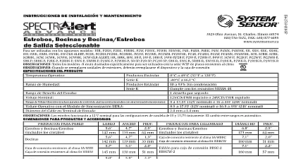
System Sensor SAA Parlantes y luces estroboscópicas de pared y techo para sistemas de señalización contra incendios series SPS y SPSV de SpectrAlert Advance

File Preview
Click below to download for free
Click below to download for free
File Data
Text Preview
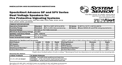
I 3825 Ohio Avenue St Charles Illinois 60174 FAX 630 377 6495 to 120 0 to 49 K Series to 93 Non condensing K Series Meets NEMA 4X IP56 rating requirements to 151 to 66 AND MAINTENANCE INSTRUCTIONS Advance SPS and SPSV Series and Ceiling Speaker Strobes for Protective Signaling Systems use with models SPSRH SPSW SPSWH SPSRV SPSWV SPSRK SPSWK SPSCR SPSCRH SPSCW SPSCWH SPSRHK SPSCRV SPSCWV SPSCWVH SPSCWK SPSCWHK SPSR P SPSRH P SPSW P SPSWH P SPSRV P SPSWV P SPSCWH P SPSCWVH P SPSCHWV P SPSRK P SPSWK P SPSCW CLR ALERT SPSW CLR ALERT SPWK R SPSWK R SPSRK R SPSCWHK P SPSWK CLR ALERT SPSCWK CLR ALERT All R models are specifically designed for use with the WTP Series of Weatherproof plates When replacing outdoor units device and back box must be replaced SPECIFICATIONS Temperature Range Voltage speakers Supervisory Voltage speakers and strobes Flash Rate Voltage strobes Frequency Range Settings Speakers Voltage Range fire alarm panels with built in sync Voltage with MDL3 Sync Module Terminal Wire Guage for Speaker Strobes and Accessories Product Speaker Strobe Speaker Strobe back box Mount Skirt Volts or 70.7 Volts nominal VDC flash per second 12VDC or FWR or regulated 24DC or FWR to 4000 Hz 1 2 1 2 watts to 17.5V 12V nominal or 16 to 33V 24V nominal including lens and speaker SPSC Speaker Strobe including lens and speaker SPSCV Speaker Strobe to 17.5V 12V nominal or 16.5 to 33V 24V nominal AWG Width back box Mount Skirt Product Box Options Indoor Products 4 21 8 or deeper Series Products red wall metal weatherproof back box white wall metal weatherproof back box white ceiling metal weatherproof back box NOTE V suffix denotes high volume device C suffix denotes ceiling device including lens and speaker including lens and speaker above finished surface of wall or ceiling Weatherproof back box dimensions do not include the two mounting tabs indoor SP and SPV Series are suitable for dry and damp environments The Series models are suitable for use in both indoor and outdoor applications This manual shall be left with the owner user of this equipment models are suitable for outdoor use in wet environments with out back box supplied with the product DESCRIPTION SpectrAlert Advance series of notification appliances offers a wide range speaker strobe products for wall and ceiling applications indoors and out The strobe portion is designed to be used in 12 or 24 volt DC or FWR wave rectified systems The speaker portion can be operated with distri amplifiers having an output voltage of either 25 or 70.7 volts its low total harmonic distortion the SpectrAlert Advance SP series of high fidelity sound output The SpectrAlert Advance SPV series offers sound output at every tap setting for applications with high ambient levels The speakers operate at any one of four input power levels These are electrically backward compatible with the previous generation of notification appliances All SpectrAlert Advance products are suit for use in synchronized systems The System Sensor MDL3 module may used to provide synchronization for the strobes Wall and ceiling products be used interchangeably wall products may be used on the ceiling and products may be used on the wall K Series products are designed to used over a wider range of temperatures and are suitable for use in wet ALARM SYSTEM CONSIDERATIONS wiring must be installed in compliance with the National Electrical Code and applicable local codes System Sensor recommends installing fire speakers in compliance with NFPA 72 ANSI UL1480 and NEC 760 DESIGN AND WIRING system designer must make sure that the total current drawn by the de on the loop does not exceed the current capability of the panel supply that the last device on the circuit is operated within its rated voltage The draw information for making these calculations can be found in the within this manual For convenience and accuracy use the voltage drop on the System Sensor website www systemsensor com or CD ROM calculating the voltage available to the last device it is necessary to the voltage drop due to the resistance of the wire The thicker the the smaller the voltage drop Wire resistance tables can be obtained from handbooks Note that if Class A wiring is installed the wire length be up to twice as long as it would be for circuits that are not fault tolerant For 24 volt applications the total number of strobes on a single NAC not exceed 40 with a maximum loop resistance of 120 ohms For 12 volt the total number of strobes must not exceed 12 with a maxi loop resistance of 30 ohms Supply power for strobe must be continuous for proper operation 1 WIRING DIAGRAM 1 SOUND LEVELS FOR EACH TRANSFORMER POWER TAP Reverberant dBA 10 ft SPSC SPSCV FROM FROM TO SPEAKER EOL TO STROBE EOL WIRING Connect the speaker as shown in Figure 1 NOTE Do not loop electrical wiring under terminal screws Wires con the device to the control panel must be broken at the device connection in order to maintain electrical supervision There are two rotary switches on the back of the product The first switch used to select either 25 or 70.7 volts input for the speaker portion The switch is used to select the input power of 1 4 1 2 1 or 2 watts diagram SPRING Shorting springs are provided between terminals 2 and 3 and between 5 and 6 of the mounting plate to enable wiring checks after the has been wired but prior to installation of the final product These will automatically disengage when the product is installed to enable of the final system 2 SHORTING SPRING SPRINGS 3 SPEAKER WATTAGE AND VOLTAGE SETTINGS Anechoic dBA 10 ft SPSC SPSCV levels exceeding 130 rated signal voltage can damage the speaker an incorrect tap connection may cause speaker damage This that if a 25V tap is selected when a 70.7V amplifier is being used damage may result Therefore be sure to select the proper taps for the voltage input power level combination being used 2 STROBE CURRENT DRAW MEASUREMENTS Current Draw mA Candela Range Candela Range Volts Volts NA SELECTION the slide switch on the rear of the product to position the desired can setting in the small window on the front of the unit All products meet light output profiles specified in the appropriate UL Standards Use Table 2 determine the current draw for each candela setting For K series products outdoors at low temperatures listed candela ratings must be reduced in with Table 3 SpectrAlert products set at 15 and 15 75 candela automatically work either 12V or 24V power supplies The products are not listed for 12V op voltages when set to any other candela settings 3 CANDELA DERATING rating at 40 K Series Outdoor Applications Only Candela Rating not use 32 Indoor Wall or Ceiling Products Attach mounting plate to junction box as shown in Figures 4 and 5 The plate is compatible 4 x 4 x 21 8 junction boxes If using a back skirt or trim ring a