System Sensor Wiring i4 to Panels with CO Trouble Zone

File Preview
Click below to download for free
Click below to download for free
File Data
| Name | system-sensor-wiring-i4-to-panels-with-co-trouble-zone-9368042157.pdf |
|---|---|
| Type | |
| Size | 1.21 MB |
| Downloads |
Text Preview
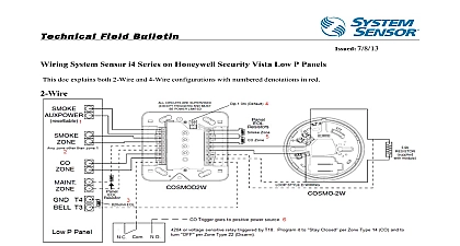
Field Bulletin 8 7 13 System Sensor i4 Series on Panels that need a CO trouble zone created document explains a configuration where a CO trouble zone is created on the panel using a shared common terminal the CO zone The example illustrated below is for a 4 wire system but the same configuration can be used with a 2 system with the only difference being the number of IDC terminals Example i4 MODULE i4 DETECTOR EOL Resistor Notes CO trouble and CO zone must be adjacent and share a common terminal on the panel To test a CO trouble signal is properly being received at the panel the detector can be without the replaceable CO cell This will cause the detector to go into CO trouble replaceable CO cell is located on the back of the detector when removed from the base Up to 12 detectors per module The COSMOD4W module is compatible with the i4 Series monoxide CO and smoke detector COSMO 4W and i3 Series smoke detector The COSMOD2W module is compatible with i4 Series carbon monoxide CO smoke detector COSMO 2W and i3 Series smoke detector 2WTA B Module sounders of both devices RRS MOD not needed Triggers are optional programmable outputs from the panel that can be used to interconnect modules with a bell output or positive voltage from the panel Please consult the manufacture for programming outputs The panel and the module must be located in the same room Ohio Avenue St Charles IL 60174 Phone 800 736 7672 Fax 630 377 6583 www systemsensor com Service 1 800 SENSOR2 736 7672


