Wheelock E50 speaker install sheet

File Preview
Click below to download for free
Click below to download for free
File Data
| Name | wheelock-e50-speaker-install-sheet-1237854069.pdf |
|---|---|
| Type | |
| Size | 700.56 KB |
| Downloads |
Text Preview
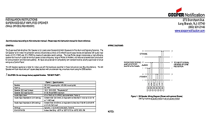
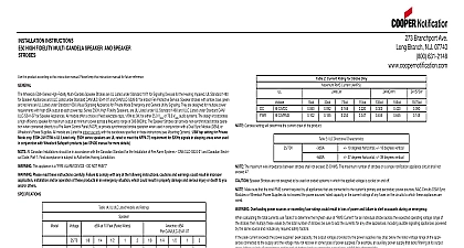
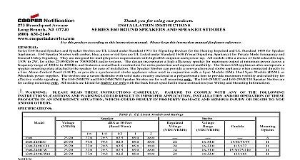
Branchport Ave Branch N J 07740 631 2148 397 5777 INSTALLATION INSTRUCTIONS Thank you for using our products SERIES E50 SPEAKERS this product according to this instruction manual Please keep this instruction manual for future reference E50 Speakers are UL Listed under UL Standard 1480 for Speaker Appliances They are designed for multiple power with high dBA output at each power tap All models offer a choice of field selectable taps 1 8W to 2W for either or 70.0VRMS audio systems The design incorporates a high efficiency speaker for maximum output at minimum power a frequency range of 400Hz to 4000Hz and features a sealed back construction for extra protection and improved audibility models are UL Listed for indoor use only with the backboxes specified in these instructions see Mounting Options All CAUTIONS and WARNINGS are identified by the symbol All warnings are printed in bold capital letters WARNING THE SPEAKER APPLIANCE IS A FIRE ALARM DEVICE DO NOT PAINT PLEASE READ THESE INSTRUCTIONS CAREFULLY FAILURE TO COMPLY WITH ANY OF THE INSTRUCTIONS CAUTIONS AND WARNINGS COULD RESULT IN IMPROPER APPLICATION AND OR OPERATION OF THESE PRODUCTS IN AN EMERGENCY SITUATION WHICH COULD IN PROPERTY DAMAGE AND SERIOUS INJURY OR DEATH TO YOU AND OR OTHERS 1 UL Listed Models and Ratings at 10 Feet Watts 79.5 82.5 85.0 All models are UL Listed for indoor use with a temperature range of 32 to 120 0 to 49 and maximum of 85 RH dBA is rated per UL Standard 1480 for Speaker Appliances Frequency range of speakers is 400 4000HZ 2007 Cooper Wheelock Inc All rights reserved F 1 of 5 INFORMATION 1.5 blocking capacitor for DC supervision of audio lines by the FACP is factory wired in series with the speaker input voltage must not exceed 33 volts DC Figure 2 1 PRECEDING SPEAKER FIRE ALARM PANEL FACP TO NEXT SPEAKER OR END OR LINE RESISTOR EOLR Series E50 Speaker models have in out wiring that accept two 12 to 18 American Gauge AWG wires at each screw Strip leads 3 8 inches and connect to terminals Break all in out wire runs on supervised as shown in Figure 2 The polarity in the wiring diagrams is for operation the appliances of Connect ground wire to backbox Install signaling appliance to backbox using mounting screws provided Check electrical ratings specified in tables 1 and 2 as appropriate to ensure proper electrical input Be sure that speaker is connected to speaker terminals only and strobe wiring is connected to strobe terminals only Check to insure that wiring at is correct IMPROPER ELECTRICAL INPUT CAN DAMAGE THE PRODUCT OR CAUSE IT TO MALFUNCTION 3 Jumper plug is used to select dBA loudness 4 Tap Settings Factory setting is 70V 1 2W F B C D E F G H A B C D E F G H Use needle nose pliers to pull and properly insert the jumper plug to the desired tap setting speaker wires to common and positive of terminal block and select the power tap terminal for 1 8W 1 4W 1 2W 1W or 25V or 70V as required see Figures 1 2 3 4 and Table 2 Each doubling of rated Watts increases sound output by 3 dBA letter corresponds to a plug position of the header located on the printed circuit board Select voltage and wattage as shown in 2 below 2 Speaker Voltage and Wattage Connection Chart The speaker strobe appliances must be set to the desired dBA sound output level before they are installed This is done by inserting jumper plugs in accordance with these instructions INCORRECT SETTINGS WILL RESULT IN IMPROPER PERFORMANCE F 2 of 5 Always operate audio amplifiers and speakers within their specified ratings Excessive input may distort sound and may damage audio equipment Improper input voltage can damage speaker If distortion is heard check for clipping of audio appliance with an oscilloscope and reduce the amplifier input level or gain level to eliminate any clipping OPTIONS The following figures show the maximum number of field wires conductors that can enter the backbox used with mounting option If these limits are exceeded there may be insufficient space in the backbox to accommodate the field wires stresses from the wires could damage the product the limits shown for each mounting option comply with the National Electrical Code NEC Cooper Wheelock use of the largest backbox option shown and the use of approved stranded field wires whenever possible to provide wiring room for easy installation and minimum stress on the product from wiring FLUSH MOUNTING NON STROBE SPEAKER BOX 8 32X1 2 PLATE MAXIMUM NUMBER OF CONDUCTORS 18 AWG 16 AWG 14 AWG 12 4 4 4 4 Surface backbox E50SB in Figure B is compatible with wiremold and conduit Mounting holes are for single gang and 10 wood screws for stud mounting If metal conduit is installed onto top and bottom conduit entrances then an grounding wire 18 AWG supplied must be connected between the top and bottom plate by using thread cutting screws to provide electrical continuity per UL 50 See Figure 5 Figure 5 F 3 of 5 PROCEDURES Check that the installed product will have sufficient clearance and wiring room prior to installing backboxes and especially if sheathed multiconductor cable or 3 4 conduit fittings are used E50 models have an integrated Speaker Mounting Plate The Speaker Mounting Plate must be oriented correctly when it is mounted to the backbox Refer to mounting options for mount the Speaker Mounting Plate to the backbox Next slide the grille over the Speaker Mounting Plate until both snaps engaged When terminating field wires do not use more lead length than required Excess lead length could result in insufficient wiring for the signaling appliance Conduit entrances to the backbox should be selected to provide sufficient wiring clearance for the installed product Do not pass additional wires used for other than the signaling appliance through the backbox Such additional wires could in insufficient wiring space for the signaling appliance Mounting hardware for each mounting option is supplied Use 2 wood screws to mount surface backbox on wall surface All models can be flush mounted to a 4 square by 2 1 8 deep backbox in the wall Figure A Use care and proper techniques to position the field wires in the backbox so that they use minimum space and produce minimum on the product This is especially important for stiff heavy gauge wires and wires with thick insulation or sheathing Use care to prevent speaker cone damage when driving screws for speaker product mounting this appliance is required to produce a distinctive three pulse Temporal Pattern Fire Alarm Evacuation Signal for total evacuation accordance with NFPA 72 the appliance must be used with a fire alarm control unit that can generate the temporal pattern signal to manufacturer installation manual for details NFPA 72 ANSI 117.1 conforms to ADAAG Equivalent Facilitation Guidelines in using fewer higher intensity strobes the same protected area Check the installation instructions of the manufacturers of other equipment used in the system for any guidelines or on wiring and or locating Notification Appliance Circuits NAC and notification appliances Some system circuits and or audio circuits for example may require special precautions to assure electrical noise immunity e g crosstalk This equipment has been tested and found