Wheelock E70H E90H speaker strobe install sheet P85327

File Preview
Click below to download for free
Click below to download for free
File Data
| Name | wheelock-e70h-e90h-speaker-strobe-install-sheet-p85327-6428105793.pdf |
|---|---|
| Type | |
| Size | 966.54 KB |
| Downloads |
Text Preview
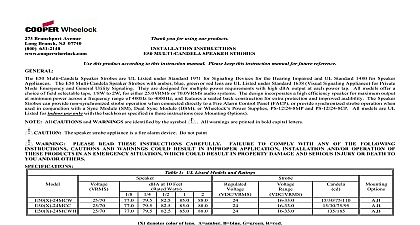
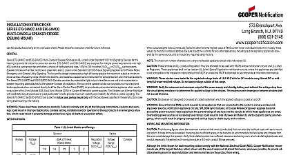
INSTALLATION INSTRUCTIONS E90H HIGH FIDELITY SPEAKER STROBES this product according to this instruction manual Please keep this instruction manual for future reference Wheelock Series E70H E90H High Fidelity Multi Candela Speaker Strobes are UL Listed under Standard 1971 for Signaling Devices for the Hearing Impaired UL Standard for Speaker Appliances and ULC Listed under Standard CAN ULC S541 07 and CAN ULC S526 07 for indoor Fire Protective Service Speaker strobes with amber blue and red lens are UL Listed under Standard 1638 Visual Signaling Appliance for Private Mode Emergency and General Utility Signaling They are designed for multiple requirements with high dBA output at each power tap All models offer a choice of field selectable taps 1 8W to 2W for either 25.0 VRMS or 70.0 VRMS audio systems The incorporates a high efficiency speaker for maximum output at minimum power across a frequency range of 300 8000Hz The speaker strobes can provide non syn strobe operation when connected directly to a Fire Alarm Control Panel FACP or provide synchronized strobe operation when used in conjunction with a Dual Sync DSM or Wheelock Power Supplies The strobes use a xenon flashtube with solid state circuitry enclosed in a polycarbonate lens to provide maximum visibility and for effective visible signaling All models are Listed for indoor use only with the backboxes specified in these instructions see Mounting Options 1 8W tap setting for Mode only E70H 241575W is UL Listed only E70H E90H series speakers are UL rated to meet the NFPA 72 requirement for 520Hz signals in sleeping areas when in conjunction with Wheelock Safepath products see SP40S manual for more details All Canadian Installations should be in accordance with the Canadian Standard for the Installation of Fire Alarm Systems CAN ULC S524 01 and Canadian Electri Code Part 1 Final acceptance is subject to Authorities Having Jurisdiction This appliance is a ALARM DEVICE DO NOT PAINT Please read these instructions carefully Failure to comply with any of the following instructions cautions and warnings could result in improper installation and or operation of these products in an emergency situation which could result in property damage and serious injury or death to you others 1A UL ULC Listed Models and Ratings Speaker Strobes Speaker Strobes at 10 Feet Rated Watts dBA PerCAN ULC S541 07 1B UL ULC Listed Models and Ratings Voltage Range 2A Current Rating for Ceiling Strobe Only RMS Current AMPS VDC VRMS 2B Current Rating for Wall Strobe Only RMS Current AMPS VDC VRMS Horizontal and Vertical Values 90 90 1 E70H Expected Light Output Figure 2 E90H Expected Light Output models are UL listed at 15cd and meet 75cd on axis Strobes produce 1 flash per second over the Voltage range All models are Listed for indoor use with a temperature range of 32 to 120 0 to 49 and maximum humidity of 93 RH The effect of shipping and stor temperatures shall not adversely affect the performance of the appliance when it is stored in the original cartons and is not subjected to misuse or abuse dBA is rated per UL Standard 1480 and ULC Standard ULC S541 07 for Speaker Appliances Frequency range of speakers is 300 8000Hz These appliances were tested to the operating voltage limits of 16 33 volts using Filtered DC or unfiltered Full Wave Rectified FWR Do not apply 80 and 110 of Check the minimum and maximum output of the power supply and standby battery and subtract the voltage drop from the circuit wiring resistance to determine the Strobes with clear and amber lens meet the required light distribution defined in UL1971 Candela ratings are for clear lens Derate approximately 25 for amber lens 55 for green 70 for blue and 80 for red Model numbers will have a letter after the voltage values for system operation voltage to the strobes A G B or R Candela setting will determine the current draw of the product 3 ULC Directional Characteristics 33 degrees horizontal 18 degrees vertical 41 degrees horizontal 31 degrees vertical The maximum wire impedence between strobes shall not exceed 35 OHMS The maximum number of strobes on a single notification appliance circuit shall not 47 Speaker Strobes are not designed to be used on coded systems in which the applied voltage is cycled on and off calculating the total currents use Table 2 to determine the highest value of Current for an individual strobe across the expected operating voltage range of strobe then multiply these values by the total number of strobes be sure to add the currents for any other appliances including audible signaling appliances powered the same source and include any required safety factors the peak current exceeds the power supplies peak capacity the output voltage provided by the power supplies may drop below the listed voltage range of the appliances connected to the and the voltage may not recover in some types of power supplies For example an auxiliary power supply that lacks filtering at its output stage either via lack of capacitance and or lack battery backup across the output may exhibit this characteristic Make sure the total RMS current required by all appliances that are connected to the system primary and secondary power sources NAC Circuits DSM Sync or Wheelock Power Supplies do not exceed the power sources rated capacity or the current ratings of any fuses on the circuits to which these appliances are Overloading power sources or exceeding fuse ratings could result in loss of power and failure to alert occupants during an emergency Does not apply to the 241575W model AND MOUNTING INFORMATION The following figures show the maximum number of field wires conductors that can enter the backbox used with each mounting option If these limits are Branchport Ave Long Branch N J 07740 800 631 2148 www coopernotification comPN P85327CCopyright 2015 Cooper Wheelock Inc Cooper Notificationfirealarmresources com there may be insufficient space in the backbox to accommodate the field wires and stresses from the wires could damage the product Check that the installed has sufficient clearance and wiring room prior to installing backboxes and conduit especially if sheathed multiconductor cable or 3 4 inch 1.9 cm conduit fittings used Although the limits shown for each mounting option comply with the National Electrical Code NEC Cooper Notification recommends use of the largest ba E70H and E90H Speaker Strobe models have in out wiring terminals that accept two 12 to 18 American Wire Gauge AWG wires at each screw terminal Strip Break all in out wire runs on supervised circuits to ensure integrity of circuit supervision as shown in Figure 3 The polarity shown in the wiring diagrams is for opera 3 8 inches 95 cm and connect to screw terminals of the appliances Refer to Sync Module instruction sheets DSM P83177 or Wheelock Power Supplies for additional information Figure 4 Figure 3 Connect ground wire to backbox Install signaling appliance to backbox using mounting screws provided Che