Wheelock Eluxa horns, horn strobes, strobes, ceiling install sheet P85756

File Preview
Click below to download for free
Click below to download for free
File Data
| Name | wheelock-eluxa-horns-horn-strobes-strobes-ceiling-install-sheet-p85756-4062987531.pdf |
|---|---|
| Type | |
| Size | 1.72 MB |
| Downloads |
Text Preview
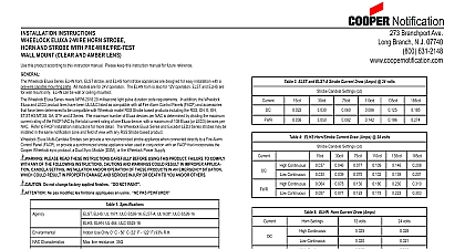
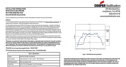
INSTALLATION INSTRUCTIONS ELUXA HORN STROBE AND STROBE WITH PRE WIRE PRE TEST MOUNT CLEAR AND AMBER LENS this product according to this instruction manual Please keep this instruction manual for future reference Wheelock Eluxa ELHNC horn ELSTC multi candela strobe and ELHS horn strobe appliances are designed for easy installation a pre wire capable mounting plate All models are for 24V operation The ELHNC horn is also for 12V operation ELSTC and are designed for ceiling mounting only ELHNC may be mounted on the wall or ceiling Wheelock Eluxa Series meets NFPA 2016 20 millisecond light pulse duration code requirements In addition the Wheelock and LED3 product lines have been UL ULC listed as compatible with all Fire Alarm Control Panels FACP and accessories have been determined to be compatible with Wheelock model RSS Strobe based products including the RSS CH E EH SA STH and Z Series The maximum number of Eluxa devices per NAC is determined by dividing the maximum rating of the FACP NAC by the total current rating of one Eluxa device with a maximum of 105 Eluxa or LED3 devices per Refer to FACP installation instructions for more detail The Wheelock Eluxa Series and Exceder LED3 Series strobes may be in the same notification zone and field of view with any RSS Strobe based product Eluxa Strobes can provide a non synchronized strobe appliance when connected directly to a Fire Alarm Control Panel or provide a synchronized strobe appliance when used in conjunction with an FACP that incorporates the Cooper Wheelock protocol a Dual Sync Module DSM or the Wheelock Power Supply PLEASE READ THESE INSTRUCTIONS CAREFULLY BEFORE USING THIS PRODUCT FAILURE TO COMPLY ANY OF THE FOLLOWING INSTRUCTIONS CAUTIONS AND WARNINGS COULD RESULT IN IMPROPER APPLICA CANDELA SETTING INSTALLATION AND OR OPERATION OF THESE PRODUCTS IN AN EMERGENCY SITUATION COULD RESULT IN PROPERTY DAMAGE AND SERIOUS INJURY OR DEATH TO YOU AND OR OTHERS Do not change factory applied finishes NOT PAINT Ne pas modifiez les finitions appliqu en usine PAS PEINTURER UL 1971 ULC S526 16 ELSTC A UL1638 ULC S526 16 1 Specifications UL 464 ULC S525 16 Use Only 0 C 50 C 32 F 122 F 93 R H Characteristics line resistance 35 Continuous Code 3 field selectable Patterns Sync Protocol Code 3 Sync Code 4 or T3 T4 Sync Selectable with DSM Operation Use Continuous Setting on ELHNC Horn Only Model Sound Output HI Low LO field selectable Power or FWR 24V Regulated 16 to 33V All models or FWR 12V Regulated 8 to 17.5V LHNC3 only Candela 30 75 110 150 177 cd field selectable is an on axis rating where the following applies effective candela rating per UL1971 2a ELHNC and ELHSC dBA Sound Output dBA Per UL 464 dBA Per ULC S525 16 output at 12V does not meet ULC S525 requirements 2b ULC Directional Characteristics 80 Degrees horizontal 80 vertical 90 Degrees horizontal 90 vertical The Code 3 temporal pattern 1 2 second on 1 2 second off 1 2 second on 1 2 second off 1 2 second on 1 1 2 off and is specified by ANSI and NFPA 72 for standard emergency evacuation signaling Available with Sync or Non Sync operation The Code 4 temporal pattern 100 ms on followed by 100 ms off for 4 cycles followed by 5 seconds of silence and repeat specified by ANSI and NFPA 720 for carbon monoxide emergency signaling Available with Sync operation only Code 4 T4 not synchronize on multi NAC multi zone installations To improve synchronization NAC must be energized simultaneously 3 ELSTC and ELSTC A Strobe Current Draw Amps 24 volts Candela Settings cd 4 ELHSC Horn Strobe Current Draw Amps 24 volts Candela Settings cd Continuous Continuous Continuous Continuous 5 ELHNC Horn Current Draw Amps Settings Continuous Continuous Continuous Continuous volts volts Candela and Horn Setting will determine the current draw of the product Strobes will produce 1 flash per second over the Voltage range Strobes are not designed to be used on coded systems in which the applied voltage is cycled on and off When calculating the total currents use Tables 3 5 to determine the highest value of RMS current for an individual appliance then these values by the total number of appliances Be sure to add the currents for any other appliances including audible appliances powered by the same source and to include any required safety factors Make sure that the total rms current required by all appliances that are connected to the system primary and secondary power Notification Appliance Circuit NAC sync module DSM sync modules or Wheelock power supplies does not exceed power sources rated capacity or the current ratings of any fuses on the circuits to which these appliances are wired Refer to Module instruction sheets DSM P83177 or Wheelock Power Supplies for additional information Check the minimum and maximum output of the power supply and standby battery and subtract the voltage drop from the circuit These appliances were tested to the regulated voltage limits of 16.0 33.0 Volts for 24 volt models and 8.0 17.5 Volts for 12 volt mod using filtered DC for the 12 volt range and either filtered DC or unfiltered DC for the 24 volt range voltage Do not apply voltage of this range These notification appliances are UL Listed as They are intended to be used with Fire Alarm Control Panels whose notification circuits are UL Listed as Refer to the FACP instructions or the Wheelock Strobe Compat Data Sheet P85328 for special application and strobe synchronization compatibility When using Horn Only models on a FACP as Special Application do not exceed 85 of Maximum NAC current Rating AMBER STROBES ARE NOT TO BE USED AS A VISUAL PUBLIC MODE ALARM NOTIFICATION APPLIANCE WARNING OVERLOADING POWER SOURCES OR EXCEEDING FUSE RATINGS COULD RESULT IN LOSS OF POWER FAILURE TO ALERT OCCUPANTS DURING AN EMERGENCY WHICH COULD RESULT IN PROPERTY DAMAGE AND INJURY OR DEATH TO YOU AND OR OTHERS at 12V ELHSC at 24V at 12V ELHSC at 24V resistance to determine the applied voltage to the strobes Branchport Ave Long Branch N J 07740 800 631 2148 www coopernotification comP85756BCopyright 2020 Cooper Wheelock Inc dba Cooper Notification All rights reserved firealarmresources com SETTINGS AND MOUNTING All strobe appliances have in out wiring terminals that accept two 12 to 18 American Wire Gauge AWG wires at each screw Strip leads 3 8 inches and connect to screw terminals Do not fully back out terminal screws Break all in out wire runs on supervised circuits to ensure integrity of circuit supervision as shown in Figure 3 The polarity shown in 2 the wiring diagram is for the operation of the appliances The polarity is reversed by the FACP during supervision T3 T4 Sync Selectable operation requires a DSM 12 24 Refer to DSM P83177 instructions All appliances must be set to T3 T4 4 T4 operation occurs when both Strobe NAC and Audible NAC remain active Code 3 T3 operation occurs when Strobe is active and Audible NAC is not acttive Audible Silence function is available only when using Continuos or T3 setting The Notification Appliance Circuits NAC to DSM must be continuous DC in Alarm Inputs to DSM may not be synchronized OPTIONS A Surface Mount with Box B Flush Mount with x 2 1 8 Back Box C Flush Mount with Back Box SQUARE BACKBOX SCREW 2 THREAD CUTTING SCREW THREAD CUTTING SCREW PRECEDING FACP SYNC MODULE NEXT SIGNAL END OF LINE EOLR 2 Horn Strobe NAC Wiring SCREW DRIVER INTO PUSH IN TO RELEASE AND LIFT UP TO REMOVE COVER PRESS IN LIFT 1 ELHSC ELSTC ELSTC A Expected Light Output 3 Wire Connection Up Up