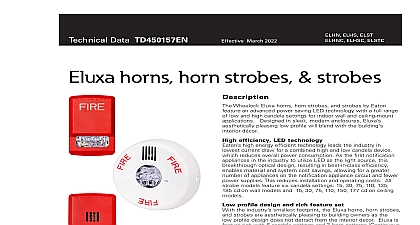
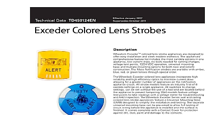
Wheelock Exceder horns, horn strobes, strobes data sheet

File Preview
Click below to download for free
Click below to download for free
File Data
| Name | wheelock-exceder-horns-horn-strobes-strobes-data-sheet-5890142367.pdf |
|---|---|
| Type | |
| Size | 1.61 MB |
| Downloads |
Text Preview
Technical Data TD450049EN Strobe Horn Strobe and Notification Appliances Wheelock Exceder Series of notification appliances a sleek modern design that will please building owners reduced total cost of ownership Installers will benefit from comprehensive feature list including the most candela options one appliance low current draw no tools needed for setting voltage test points 12 24 VDC operation universal base and multiple mounting options for both new and construction Wheelock Exceder Series incorporates high reliability and high optics to minimize current draw allowing for a greater of appliances on the notification appliance circuit All strobe feature an industry first of 8 candela settings on a single Models with an audible feature 3 sound settings 90 95 dB All switches to change settings can be set without the use a tool and are located behind the appliance to prevent tampering models feature voltage test points to take readings with a meter for troubleshooting and AHJ inspection Wheelock Exceder Series of wall and ceiling notification feature a Universal Mounting Base UMB designed simplify the installation and testing of horns strobes and horn strobes The separate universal mounting base be pre wired to allow full testing of circuit wiring before the is installed and the surface is finished It comes complete a Contact Cover for protection against dirt dust paint and to the contacts The Contact Cover also acts as a device to allow pre wire testing for common wiring issues Contact Cover is polarized to prevent it from being installed and prevents the appliance from being installed while it on the UMB When the Contact Cover is removed the circuit will an open until the appliance is installed The UMB allows for installation and easy replacement of appliances if Wall models provide an optional locking screw for extra installation while the ceiling models provide a captivated to prevent the screw from falling during installation November 2016 Supersedes October 2014HN SeriesHS SeriesST Seriesfirealarmresources com Environmentally friendly Low current draw Up to 9 models now in 1 appliance draw a 12 24VDC on a single appliance Easy to remember model numbers Patented read these specifications and associated installation instruc before using specifying or installing this product Visit Eaton com for current installation instructions Notes Strobes are designed to flash at 1 flash per second minimum over Voltage Range All candela ratings represent minimum effective strobe intensity on UL Standard 1971 Series Exceder Strobe products are Listed under UL Standards and 464 for indoor use with a temperature range of 32 to 0 to 49 and maximum humidity of 93 2 UL 85 UL 1971 Series Exceder horns are under UL Standard 464 for audible appliances Indoor use only and requirements Synchronize using the Wheelock Sync Modules or panels with Wheelock Patented Sync Protocol Compatible with UL Voltage using filtered VDC or VRMS input voltage Strobes produce 1 flash per second over the range UL 1971 UL 464 ULC CSFM FM ADA NFPA ANSI OSHA RoHS Data TD450049EN November 2016 Sleek modern aesthetics Finger slide switches Voltage test points Multiple voltages 3 Audible settings 90 95 99 dB leading candela settings on 1 device Wall 15 1575 30 75 95 110 135 185 Ceiling 15 30 60 75 95 115 150 177 Universal mouting base Ceiling and wall Mounts to 5 backbox types 1 gang 2 gang 4 square octal 4 octal 100mm for international customers mounting base cover base for wall and ceiling with 5 mounting options Voltage test points for quick troubleshooting and easy spot wall models only www eaton comHN SeriesHS SeriesST Seriesfirealarmresources com Data TD450049EN November 2016 1 Strobe Ratings per UL Standard 1971 Max Currenta VDC 24 FWR Voltage VDC 2 Horn Strobe Ratings per UL 1971 Anechoic at 24 VDC Max Currenta at Anechoic 99 dBA VDC Voltage VDC Voltage VDC Max Currenta at Anechoic 95 dBA VDC Max Currenta at Anechoic 90 dBA VDC VDC VDC VDC VDC Voltage VDC UL max current rating is the maximum RMS current within the listed voltage range 16 33 VDC for 24 VDC units For strobes the UL max current is usually at the minimum listed voltage 16 VDC for 24 VDC For audibles the max current is usually at the maximum listed voltage 33 VDC for 24 VDC units For unfiltered ratings see installation instructions 3 Horn Ratings per UL Anechoic Voltage VDC dB dB dB Legend Horn White Strobe Horn Strobe Ceiling Mount Red Agent Lettering strobes only Alert Lettering strobes only No Lettering strobes only 4 Specification Ordering Information w DSM or Power 1 STRC Strobe Red Ceiling Mount 2 HSR Horn Strobe Red Wall Mount 3 HSW Horn Strobe White Wall Mount 4 STW AL Strobe White Wall Mount Alert Lettering Strobe Candela Strobes 15 1575 30 75 95 110 135 185 15 30 60 75 95 115 150 177 15 1575 30 75 95 110 135 185 12 VDC models feature 15 15 75 settings UMB Universal Mounting Base HSR HSWC www eaton comHN SeriesHS SeriesST Seriesfirealarmresources com Data TD450049EN November 2016 and Engineers Specifications notification appliances shall be Wheelock Exceder Series HS Audible Strobe appliances Series ST Visual Strobe appliances and Series Audible appliances or approved equals The Series HS and ST Strobes shall be listed for UL Standard 1971 Emergency Devices for the for Indoor Fire Protection Service The Series HS and HN Audibles shall be UL Listed under Standard 464 Fire Protective All Series shall meet the requirements of FCC Part 15 Class B All inputs shall be compatible with standard reverse polarity of circuit wiring by a Fire Alarm Control Panel FACP with the ability to operate from 8 to 33 VDC Indoor wall models shall voltage test points for easy voltage inspection Series HS Audible Strobe and ST Strobe appliances shall produce a flash rate of one 1 flash per second over the Regul


