Wheelock S8 speaker install sheet P84478

File Preview
Click below to download for free
Click below to download for free
File Data
| Name | wheelock-s8-speaker-install-sheet-p84478-6390278451.pdf |
|---|---|
| Type | |
| Size | 1.00 MB |
| Downloads |
Text Preview
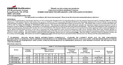
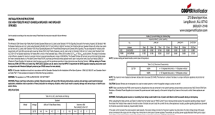
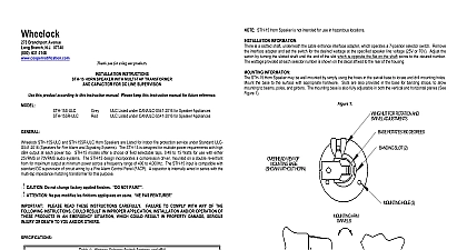
Branchport Avenue Branch NJ 07740 631 2148 SERIES S8 EIGHT INCH SPEAKER AND MULTI CANDELA SPEAKER STROBE INSTALLATION INSTRUCTIONS Thank you for using our products CEILING MOUNT VERSION this product according to this instruction manual Please keep this instruction manual for future reference S8 70 25 Eight Inch Speaker S8 24MCC Multi Candela Eight Inch Speaker Strobe and S8 24MCCH Multi High Candela are UL Listed under Standard 1971 Devices for the Hearing Impaired and Standard 1480 Speakers for Fire Protective Signaling Systems for indoor fire protection service The S8 24MCC S8 24MCCH with amber red blue or green lens is UL Listed under Standard UL1638 Visual Signaling Appliance for Private Mode Emergency and General Signaling The S8 Eight Inch Speaker is designed for multiple power requirements with high dBA output at each power tap and offers a choice of field taps 1 4W to 8W for either 25.0VRMS or 70.0VRMS audio systems The speaker has a molded flame retardant cone In order to maintain proper UL 1480 listing the CBB 8 Speaker Backbox available separately must be installed The CBB 8 Backbox is required for use in plenums that are part of return air handling systems S8 24MCC Strobe provides four selectable light output intensities 15,30,75,95cd in one unit The S8 24MCCH Strobe provides two selectable light intensities in one unit The Strobe can provide a non synchronized strobe appliance when connected directly to a fire alarm control panel FACP or provide a strobe appliance when used in conjunction with a Sync Module SM Dual Sync Module DSM or Wheelock Power Supplies The strobe uses a flashtube with solid state circuitry enclosed in a polycarbonate lens to provide maximum visibility and reliability for effective visible signaling The S8 70 25 and S8 24MCCH are Listed for indoor use ceiling mount only with the backboxes specified in these instructions see wiring and mounting information series speakers are UL rated to meet the NFPA 72 requirement for 520Hz signals in sleeping areas when used in conju nction with Wheelock Safepath see SP40S manual for more details PLEASE READ THESE INSTRUCTIONS CAREFULLY FAILURE TO COMPLY WITH ANY OF THE FOLLOWING CAUTIONS AND WARNINGS COULD RESULT IN IMPROPER APPLICATION CANDELA SETTING INSTALLATION AND OR OF THESE PRODUCTS IN AN EMERGENCY SITUATION WHICH COULD RESULT IN PROPERTY DAMAGE AND SERIOUS OR DEATH TO YOU AND OR OTHERS 1 UL Listed Models and Ratings Speaker at 10 Feet Watts Fig 1 Fig 1 Fig 1 The strobe will produce 1 flash per second over the Regulated Voltage range The Series S8 70 25 S8 24MCC and S8 24MCCH are UL Listed for indoor use with a temperature range of 32 to 120 0 to 49 and maximum with clear and amber lens meet the required light distribution patterns defined in UL 1971 A 10 blocking capacitor for DC supervision of audio lines by the FACP is factory wired in series with the speaker input The maximum supervision voltage is volts DC Frequency range of speakers is 400 4000Hz Ratings listed in Table 1 are for clear lens Derate approximately 25 for amber lens 55 for green 70 for blue 80 for red of 85 RH THESE APPLIANCES WERE TESTED TO THE REGULATED VOLTAGE LIMITS OF 16.0 33.0 VOLTS FOR 24V MODELS USING DC OR UNFILTERED FULL WAVE RECTIFIED VOLTAGE DO NOT APPLY VOLTAGE OUTSIDE OF THIS RANGE CHECK THE MINIMUM AND MAXIMUM OUTPUT OF THE POWER SUPPLY AND STANDBY BATTERY AND SUBTRACT THE DROP FROM THE CIRCUIT WIRING RESISTANCE TO DETERMINE THE APPLIED VOLTAGE TO THE STROBES THE MAXIMUM IMPEDANCE BETWEEN STROBES SHALL NOT EXCEED 35 OHMS CANDELA SETTING WILL DETERMINE THE CURRENT DRAW OF THE PRODUCT 2 UL Current Ratings with Strobe Only RMS Current AMPS Voltage MAKE SURE THAT THE TOTAL RMS CURRENT REQUIRED BY ALL APPLIANCES THAT ARE CONNECTED TO THE PRIMARY AND SECONDARY POWER SOURCES NAC CIRCUITS SM DSM SYNC MODULES OR WHEELOCKS POWER SUPPLIES NOT EXCEED THE POWER SOURCES RATED CAPACITY OR THE CURRENT RATINGS OF ANY FUSES ON THE CIRCUITS TO WHICH APPLIANCES ARE WIRED OVERLOADING POWER SOURCES OR EXCEEDING FUSE RATINGS COULD RESULT IN LOSS OF POWER FAILURE TO ALERT OCCUPANTS DURING AN EMERGENCY WHICH COULD RESULT IN PROPERTY DAMAGE AND SERIOUS INJURY DEATH TO YOU AND OR OTHERS 2015 Cooper Wheelock Inc All rights reserved P84478J 1 of 4 calculating the total currents Use Table 2 to determine the highest value of Current for an individual strobe a cross the expected operating voltage of the strobe then multiply these values by the total number of strobes be sure to add the currents for any other appliances including audible signaling powered by the same source and include any required safety factors The maximum number of strobes on a single notification appliance circuit shall not exceed 50 The Strobe is not designed to be used on coded systems in which the applied voltage is cycled on and off INFORMATION 1 The maximum number of field wires conductors that can enter the CBB 8 or other listed equivalent backbox shall comply with the National Code NEC If this limit is exceeded there may be insufficient space in the backbox to accommodate the field wires Stresses from the wires could the product Wheelock also recommends the use of approved stranded field wires whenever possible to provide additional wiring room for easy installation and minimum on the product from wiring S8 70 25 S8 24MCC and S8 24MCCH models are designed to mount flush in a hung tile ceiling The CBB 8 or other listed equivalent backbox is required per Standard 1480 Speakers for Fire Protective Signaling Systems When the speaker and backbox cannot be installed directly through a ceiling tile a support bridge be used Refer to P84239 and P81490 for additional mounting information INFORMATION 2 3 The Low Profile Speaker Strobe model has in out wiring terminals accept two 12 to 18 American Wire Gauge AWG wires each screw terminal Strip leads 3 8 inches and connect to terminals Break all in out wire runs on supervised circuits to assure integrity circuit supervision as shown in Figure 3 The polarity shown in wiring diagrams is for operation of the appliances Connect speaker wires to common and positive of terminal block select the power tap terminal for 1 8W 1 4W 1 2W 1W 2W or 8W 25V or 70V as required see Figures 2 3 4 5 and 4 Refer to Sync Module instruction sheets SM P83123 DSM P83177 or power supplies for additional information Connect ground wire to backbox Install signaling appliance to backbox using mounting screws provided THE SPEAKER STROBE APPLIANCE MUST BE FIELD SET TO THE DESIRED dBA SOUND OUTPUT LEVEL BEFORE IT IS THIS IS DONE BY PROPERLY INSERTING JUMPER PLUGS IN ACCORDANCE WITH THESE INSTRUCTIONS INCORRECT WILL RESULT IN IMPROPER PERFORMANCE WHICH COULD RESULT IN PROPERTY DAMAGE AND SERIOUS INJURY OR TO YOU AND OR OTHERS 4 Jumper plug is used to select tap settings which dBA loudness 5 Tap Settings Factory setting is 70V 0.5W H letter corresponds to a plug position of the header located on the circuit board Select voltage and wattage as shown in Table 3 Use needle nose pliers to pull and properly insert the jumper plug to the desired tap setting J 2 of 4 STROBE COM OPTIONAL FROM PRECEDING SPEAKER OR FIRE ALARM CONTROL PANEL FACP FROM PRECEDING STROBE APPLIANCE OR SYNC MODULE TO NEXT APPLIANCE OR EOLR TO NEXT SPEAKER OR END