Wheelock TB telbell install sheet P81897

File Preview
Click below to download for free
Click below to download for free
File Data
| Name | wheelock-tb-telbell-install-sheet-p81897-0594236718.pdf |
|---|---|
| Type | |
| Size | 661.10 KB |
| Downloads |
Text Preview
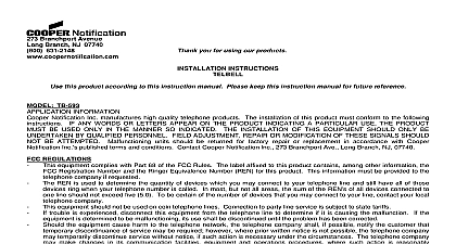
Branchport Avenue Branch NJ 07740 631 2148 Thank you for using our products INSTRUCTIONS BELL this product according to this instruction manual Please keep this instruction manual for future reference NO TB 592 TB series Telbells are designed to provide a loud attention getting bell sound for use in noisy locations or for wide area coverage It includes an adjustable tamper resistant volume control Telbell utilizes the motor driven mechanism concept that incorporates a high torque permanent motor and a 6 aluminum shell to produce higher sound output and lower resonant frequency than conventional mechanical bells The TB are designed for use with telephone communications systems whose ringing voltages are from 18 30VAC DC are attractively packaged for convenient indoor or outdoor surface mounting Wiring is easy because a modular telephone jack is provided they provide screw terminals for hard wiring and a knockout for 1 2 conduit THESE INSTRUCTIONS CAREFULLY BEFORE USING THIS PRODUCT All CAUTIONS and WARNINGS are identified by the symbol INFORMATION TB series Telbells are intended for surface mounting To install the Telbell follow instructions below Modular Connection Figure 1 2 All warnings are printed in bold capital letters the center bolt to remove the bell shell Mount the base to the desired location using mounting hardware suitable for the mounting surface material Mount bell shell to housing with center bolt Be sure shell is properly aligned with housing hole in bell shell must be aligned with guide pin on bell housing the telephone cord through the bushing provided and plug the telephone cord into the unit modular phone jack then plug the into the backbox per Figure 2 by having someone ring your telephone to make sure the signal functions properly factory volume control setting is at maximum Readjust volume as required For tamper resistant volume setting remove volume shaft by pulling straight out the center bolt to remove the bell shell the bell housing by unscrewing all four screws Disconnect the red and black wires by unplugging from the PC Board Wire Connection Figures 3 4 Mount the backbox to the desired location using mounting hardware suitable for the mounting surface material conduit the 24VDC wires through the bushing provided and connect wires to terminal TB1 marked T and R respectively Then plug the into the phone jack opening of the backbox See Figure 4 conduit the knock out in the top of backbox Be careful not to damage PC Board components The knock out opening is sized for 1 2 and matching connector Be sure that proper water tight conduit fitting is used to connect to the bell backbox for outdoor application 24VDC wires to terminal TB1 marked T and R respectively Telbells are not polarity sensitive They will function even though the polarity is reversed red and black wires to pins marked red and black respectively on the PC Board the bell housing to the backbox with the four screws Mount bell shell to housing and secure with center bolt Be sure shell is properly aligned with housing Pin hole in bell shell must be aligned with guide pin on bell housing the bushing into the phone jack opening of the backbox by having someone ring your telephone to make sure the signal functions properly factory volume control setting is at maximum Adjust volume as required For tamper resistant volume setting remove volume control by pulling straight out At low input voltages and low volume settings the volume control may have to be adjusted to obtain the desired sound output Telbell does not eliminate existing telephone ringers Such ringers can be disconnected when Telbell is installed 2011 Cooper Wheelock Inc dba Cooper Notification All rights reserved N These devices are not intended for use in hazardous locations as defined by the National Electrical Code NEC and by the National Fire Association NFPA Contact Wheelock Inc for information on explosion proof devices designed for hazardous locations 1 Performance Specifications Number Input Voltage Voltage Range Current at Nominal Input Voltage Pressure Level Min Max Volume ON Cycle OFF Cycle Size Impedance Jack at 1 Meter Seconds Seconds Aluminum Infinite Blocking Capacitor RJ11C PIN 2 Black PIN 5 Yellow TOP MARKING 1 2 CONDUIT SHELL PIN FT MODULAR CORD PIN HOLE WITH GUIDE PIN 1 Removal of Bell Shell 2 Modular Connection TELEPHONE SYSTEM ALERT CARTRIDGE SERVICE MODULE SUPPLEMENTARY ALERT AS APPLICABLE TOP MARKING 1 2 CONDUIT BOARD CONDUIT ONLY KNOCKOUTS FOR CONDUIT CONNECTOR SHELL CONDUIT BOARD CONTROL R PIN SCREWS 3 Removal of Bell Shell and Housing 4 Hard Wire Diagram PIN HOLE WITH GUIDE PIN WIRE ENTRANCE ONLY SHOWN WITH BELL HOUSING REMOVED N MATERIAL EXTRAPOLATED FROM THIS DOCUMENT OR FROM WHEELOCK MANUALS OR OTHER DOCUMENTS DESCRIBING THE FOR USE IN PROMOTIONAL OR ADVERTISING CLAIMS OR FOR ANY OTHER USE INCLUDING DESCRIPTION OF THE APPLICATION OPERATION INSTALLATION AND TESTING IS USED AT THE SOLE RISK OF THE USER AND WHEELOCK WILL HAVE ANY LIABILITY FOR SUCH USE WARRANTY Wheelock Inc dba Cooper Notification and Cooper Notification Inc each a products must be used within their published and must be PROPERLY specified applied installed operated maintained and operationally tested in accordance with these instructions the time of installation and at least twice a year or more often and in accordance with local state and federal codes regulations and laws application installation operation maintenance and testing must be performed by qualified personnel for proper operation in accordance all of the latest National Fire Protection Association NFPA Underwriter Laboratories UL National Electrical Code NEC Occupational Safety Health Administration OSHA local state county province district federal and other applicable building and fire standards guidelines regulations and codes including but not limited to all appendices and amendments and the requirements of the local authority having jurisdiction AHJ Seller when properly specified applied installed operated maintained and operationally tested as provided above are warranted against mechanical electrical defects for a period of a three 3 years from date of manufacture with respect to MEDC and Seller Industrial Signals and Seller Fire and Notification Appliances and Devices or b one 1 year from date of manufacture with respect to Waves and SafePath Voice Evacuation and Notification Systems date of manufacture is determined by date code Correction of defects by repair or replacement shall be at Seller sole and shall constitute fulfillment of all obligations under this warranty THE FOREGOING LIMITED WARRANTY SHALL IMMEDIATELY IN THE EVENT ANY PART NOT FURNISHED BY SELLER IS INSTALLED IN THE PRODUCT THE FOREGOING LIMITED SPECIFICALLY EXCLUDES ANY SOFTWARE REQUIRED FOR THE OPERATION OF OR INCLUDED IN A PRODUCT SELLER NO REPRESENTATION OR WARRANTY OF ANY OTHER KIND EXPRESS IMPLIED OR STATUTORY WHETHER AS TO FITNESS FOR A PARTICULAR PURPOSE OR ANY OTHER MATTER ARE SOLELY RESPONSIBLE FOR DETERMINING WHETHER A PRODUCT IS SUITABLE FOR THE USER PURPOSES OR WHETHER WILL ACHIEVE THE USER INTENDED RESULTS THERE IS NO WARRANTY AGAINST DAMAGE RESULTING FROM MISAPPLIACATION SPECIFICATION ABUSE ACCIDENT OR OTHER OPERATING CONDITIONS BEYOND SELLER CONTROL DOES NOT WARRANT THAT THE OPERATION OF THE SOFTWARE WILL BE UNINTERRUPTED OR ERROR FREE OR THAT THE WILL MEET ANY OTHER STANDARD OF PERFORMANCE OR THAT THE FUNCTIONS OR PERFORMANCE OF THE SOFTWARE