DSC PC5400 v3 0 DVACS IM EN NA

File Preview
Click below to download for free
Click below to download for free
File Data
| Name | dsc-pc5400-v3-0-dvacs-im-en-na-2687093145.pdf |
|---|---|
| Type | |
| Size | 762.90 KB |
| Downloads |
Text Preview
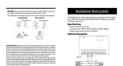
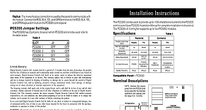
Installation Sur Gard DVACS Version 3.0 TAFNZ W A R N I N G cid 127 refer to the System Installation Manual for information on regarding product use and function and information on limitations as to liability of the manufacturer of Contents 3 Specifications 3 3 Hook up Diagram Section Descriptions Worksheets PC1555 1565 PC5008 PC5010 PC5015 PC5020 Sections 7 A DVACS Reporting Type Tables B PC580 585 PC1555 1565 PC5008 PC5010 PC5020 DVACS Default Reporting Codes compatible alarm control panels to be to a DVACS communications network Specifications 4 wire QUAD hook up to keybus Normal current draw of 35 mA Tamper and Trouble reporting codes Maximum cable length 61m 200 ft connected to a DVACS network Automatic programming for DVACS function and reporting codes Programmable response type to all calls Monitoring for DVACS line fault Module self diagnostics Products PC580 585 PC1555 1565 PC5008 PC5010 PC5015 PC5020 the Cabinet mounting a new cabinet for the PC5400 a dry location close to the F1 F2 subset mount the PC5400 Press the four white circuit board stand offs the raised mounting holes from the back the cabinet Hold the cabinet in position and pull the wires the cabinet Mount the cabinet securely to the wall using mounting screws provided Use the wall anchors when securing the to the drywall plaster concrete brick or similar surfaces With the cabinet mounted press the PC5400 onto the stand offs to the Hook up Diagram included in this BLK YEL and GRN Terminals the RED BLK YEL and GRN terminals to RED BLK YEL and GRN terminals on the panel Refer to the control panel Manual for complete instructions on wiring and T2 T1 and T2 to a normally closed switch will be used to monitor tampers If no tamper is desired place a wire between T1 and T2 Hook up Diagram Used Section Descriptions you will be connecting the PC5400 to a PC580 585 PC1555 1565 PC5008 PC5010 PC5015 or control panel access the PC5400 programming sections at a system keypad by entering Code 803 Then enter the 2 digit number of the section you want to program 10 13 Wireless Miscellaneous Reporting Codes the DVACS reporting codes in these sections see DVACS Transmission Table for Transmission To have the PC5400 transmit a pre programmed code from the internal table leave the at the default value FF Default reporting codes are listed in the Appendices B and C To prevent the PC5400 from reporting an event program the code as 00 To have the PC5400 transmit a different code program a value from 01 FE 14 16 PC5200 Reporting Codes 17 Reporting Codes 18 Reporting Types 20 23 Wireless Miscellaneous Reporting Types programming the Reporting Types sections you can add additional information to each transmission example you can program the reporting code for zone 1 as 01 and the reporting type for zone 1 as to indicate that zone 1 is a fire zone Refer to the DVACS Reporting Type tables on pages 24 27 To have the PC5400 transmit a pre programmed code from the internal table leave the at the default value FF Default reporting types are listed in the Appendix A To have the PC5400 transmit a different code program a value from 00 7F Do not program values above 7F 24 26 PC5200 Reporting Types 31 34 Zone Definitions sure that the zone definitions match those programmed in the control panel 40 DVACS ID Code the DVACS ID code in this section This code identifies a PC5400 module on a DVACS subset which poll from a F2 node the module will respond to Valid entries are 01 F0 41 All Call Select this section to program which all call response the PC5400 will have The options are no response on any all call on all call 1 only on all call 2 only on both all calls modules with odd numbered ID codes see section 40 respond to All Call 1 Modules with even ID codes respond to All Call 2 E g a module withID code 03 will respond to All Call A module with ID code 04 will respond to All Call 2 42 Miscellaneous Transmission Options 1 Turn this option ON to have the PC5400 send alarms during an all call Turn this option OFF to the PC5400 send alarms and restorals during an all call 2 Turn this option ON to have the PC5400 report which zones have been bypassed Turn this OFF for prevent the PC5400 from reporting which zones have been bypassed 3 Turn this option ON to have the PC5400 report openings and closings Turn this option OFF to prevent the PC5400 from reporting openings and closings 43 68 Reporting Codes the DVACS reporting codes in these sections see DVACS Transmission Table for Transmission To have the PC5400 transmit a pre programmed code from the internal table leave the at the default value FF Default reporting codes are listed in the Appendices B and C To prevent the PC5400 from reporting an event program the code as 00 To have the PC5400 transmit a different code program a value from 01 FE 69 94 Reporting Types programming the Reporting Types sections you can add additional information to each transmission example you can program the reporting code for zone 1 as 01 and the reporting type for zone 1 as to indicate that zone 1 is a fire zone Refer to the DVACS Reporting Type tables on pages 24 27 To have the PC5400 transmit a pre programmed code from the internal table leave the at the default value FF Default reporting types are listed in the Appendix A To have the PC5400 transmit a different code program a value from 00 7F Do not program values above 7F If you change any of the above options from the default settings test the PC5400 to make sure is operating as desired Worksheets PC1555 1565 PC5008 PC5010 PC5015 or PC5020 Programming Sections you will be connecting the PC5400 to a PC580 585 PC1555 1565 PC5008 PC5010 PC5015 or control panel access the PC5400 programming sections at a system keypad by entering Code 803 Then enter the 2 digit number of the section you want to program Future Use Future Use Future Use Future Use Key 5 Key 6 Key 7 Key 8 Key 13 Key 14 Key 15 Key 16 On Off Line Future Use Future Use Future Use I I I I I I I I I I I I Key 1 Key 2 Key 3 Key 4 Key 9 Key 10 Key 11 Key 12 Keypad 1 Keypad 2 Keypad 3 Keypad 4 Keypad Low Battery Reporting Codes I I I I I I I I I I I I I I I I I I I I I I I I Key 1 8 Low Battery Reporting Codes I I I I I I I I I I I I Key 9 16 Low Battery Reporting Codes I I I I I I I I I I I I I I I I I I I I I I I I Option Reporting Codes I I I I I I I I I I I I 1 4 Supervisory and Tamper Reporting Codes I I I PC5200 1 Supervisory I I I PC5200 2 Supervisory I I I PC5200 3 Supervisory I I I PC5200 4 Supervisory 1 4 AC and Battery Trouble Reporting Codes I I I PC5200 1 AC Trouble I I I PC5200 2 AC Trouble I I I PC5200 3 AC Trouble I I I PC5200 4 AC Trouble Code Code to Close Buffer 75 Full I I I I I I I I I I I I PC5200 1 Tamper