Fike System Sensor 100 Series Low Profile Plug in Smokes A05-0182

File Preview
Click below to download for free
Click below to download for free
File Data
| Name | fike-system-sensor-100-series-low-profile-plug-in-smokes-a05-0182-2756139480.pdf |
|---|---|
| Type | |
| Size | 816.38 KB |
| Downloads |
Text Preview
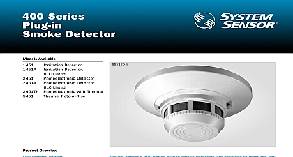
100 Series Plug in Detector Available Ionization Detector Photoelectronic Detector suf denotes ULC listed product Overview low pro design housing design for both ion and models with 400 Series product LEDs blink in standby providing 360 sensitivity metering of detector to the requirements of NFPA 72 range of adapter bases available built in shorting spring Sensor 100 Series Plug in Smoke Detectors offer superb performance and reli in a pro which is just 1.6 4.2 cm deep Model 1151 ionization sensor Model 2151 photoelectronic sensor share the same sleek low pro design and be used with a variety of different adapter bases in several wiring con voltages Other features include low current draw stable performance in high air built in tamper resistant base design remote LED option removable cover built in test switch 100 Series is designed to meet the performance criteria designated by UL sensing chambers are sealed against back pressure air dirt and This chamber is protected by a mesh screen which can be cleaned or Additional key features include interchangeable ion and photo heads a of mounting bases and a full line of accessories 100 Series ionization smoke detectors include a single source dual chamber that senses smoke particles This chamber exhibits excellent stability sig reducing nuisance alarms and provides good performance at higher air 100 Series photoelectronic smoke detectors contain a unique optical sensing designed to sense smoke particles produced by a wide range of combus sources A custom integrated circuit incorporates signal processing to reduce alarms Speci ionization detector model shall be equipped with a unipolar sensing chamber The nominal sensi of the detector shall be 1.0 ft as measured in a UL box and shall not alarm when it is exposed to wind up to 500 feet per minute The photoelectronic detec model shall have a nominal sensitivity of 3.0 ft as in a UL smoke box with a nominal signal to noise of 2.0 Both ionization and photoelectronic detector shall be available The detector shall be equipped a light emitting diode LED that is visible from the This LED shall blink every ten seconds to indicate that detector is operational in standby and latch on as a indication of alarm The detector shall be capable of an output voltage to an optional remote LED as an indication of its status The photoelec detector shall include built in circuitry that performs functional test of all detection circuits at least once every seconds without the need for generating smoke It shall possible to perform a calibrated sensitivity and perform test on the detector without the need for generating The test method shall test all detector circuits The screen and cover assembly shall be easily removable cleaning or replacement It shall maintain stable opera when it is exposed to wind gusts of up to 3000 feet per The detector shall use a plug in low pro design is both unobtrusive and aesthetically pleasing A line of bases for a variety of applications shall be available use with the detectors Wire connections shall be made means of a clamping plate and screw These bases shall for mounting directly to a surface or to a 31 or 4 box retardant thermoplastic to 120 0 to 49 Listed Velocity Range 500 fpm 0 2.5 m s 3000 fpm 0 15.2 m s Range 93 RH noncondensing Detector Spacing smooth ceilings as defined in NFPA 72 spacing of 30 feet 900 sq ft be used as a guide Other spacing may be used depending on ceiling high air movements and other conditions or response requirements Limit Resistor Type A C A C A Supervisory C Voltage Draw on Alarm mA mA AC Max contingent on panel compatibility Must be limited by control panel base Contact Ratings Resistive or Inductive 60 power factor load A C at 30 VAC DC at 110VDC 2.0A at 30VDC at 125VAC 2.0A at 30VAC Box Selection Guide Model Number Gang Octagon Octagon Square mm mm mm depth contingent on base and wire size Refer to National Electrical Code or local applicable codes for appropriate recommendations Voltage Alarm Current Adapter Base Selection Guide following Current Standby Standby Ion 3 Photo Weight oz 102 g h 42 mm mm dia unflanged base mm dia flanged base Base Selection Guide Model Number Type Series Adapter Base Mounting Guide or B401 Wiring Diagram FAULT TOLERANT WIRING Wiring Diagram VAC C CIRCUIT VAC C CIRCUIT Wiring Diagram CIRCUIT BLK Wiring Diagram NFPA CLASS WIRING Information No ionization detector Must be mounted to one of the Series or B400 Series bases listed in Adapter Base Guide photoelectronic detector Must be mounted to one of B100 Series or B400 Series bases listed in Adapter Base Guide replacement flange for B400 Series flanged bases annunciator for 2 or 4 wire systems 3 32V Use with ion photo plug in detectors Fits standard single gang electrical base Requires an external 24 VDC power supply Mounts to square electrical box 11 minimum depth 21 recommended Detector sensitivity test tool See below Use with most analog digital multimeters Satisfies NFPA 72 requirement for sensitivi testing face mounting kit provides for entry of sur face wiring conduit use with B401 or B401R mounting bases only End of line relay for power supervision 12 24 VDC systems ionization detector ULC listed photoelectronic detector ULC listed Test magnet Test magnet with 32 telescoping handle removal tool Allows installation and or removal of 100 detector heads from base in high ceiling installations when with XP 4 pole for XR 2 Comes in three 5 ft sections Replacement dust cover for 100 Series smoke detectors mounting kit for 2151 detector B