Fike System Sensor 400 Series Plug in Smokes A05-0205

File Preview
Click below to download for free
Click below to download for free
File Data
| Name | fike-system-sensor-400-series-plug-in-smokes-a05-0205-9745328061.pdf |
|---|---|
| Type | |
| Size | 731.94 KB |
| Downloads |
Text Preview
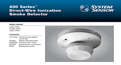
400 Series Detector Available Detector Detector Listed Detector Detector Listed Photoelectronic with Thermal Rate of Rise Overview standby current visible LEDs in standby provide a 360 viewing variety of mounting bases with shorting spring head plugs easily into base test switch sensitivity metering of detector meet the requirements of NFPA 72 tamper resistant feature screws for easy wiring recessed mounting cover and insect screen cleaning Sensor 400 Series plug in smoke detectors are designed to meet the per criteria designated by UL ULC The ion and photo units have a sensing sealed from back pressure air flow dirt and insects This chamber is pro by a fine mesh screen which can be cleaned or replaced Additional key include a recessed mounting option interchangeable ion photo or ther detectors a variety of mounting bases and a full line of optional accessories All 400 Series ionization smoke detectors include a specially designed source dual unipolar detector chamber design which will sense the presence of particles produced by fast combustion as well as slow smoldering fires This exhibits increased stability significantly reduces nuisance alarms and pro better performance at higher air velocities All 400 Series photoelectronic smoke detectors contain an optical chamber designed to sense the presence of smoke particles produced by a range of combustion sources A custom integrated circuit incorporates signal to reduce false alarms The 400 Series thermal rate of rise with fixed heat detector contains a dual thermistor heat sensing circuit to provide maximum performance and state reliability The Model 5451 is designed to initiate an alarm at 135 and respond to a temperature increase in excess of 15 per minute This enables the detector to communicate an alarm to the central control panel prior to reaching static set point for these high rates of rise providing a timely response to both and slow temperature increases This model should be used in applications rapid response is desired and where rapid temperature increases would only caused by a fire emergency Base Selection Guide Model Resistor Type Draw Alarm mA A C A C A mA AC Max base Although B401B and B401 bases are capable operating at 12 and 24 VDC they cannot be with the 5451 in 12 V applications contingent on panel compatibility be limited by control panel Contact Ratings A C or Inductive power factor load at 30 VAC DC at 110VDC 2.0A at 30VDC at 125VAC 2.0A at 30VAC 2 wire C Box Selection Guide Yes Octagon Octagon Square mm mm mm Box depth contingent on base and wire size to National Electrical Code of local applicable codes for appropriate recommendations Voltage Alarm Current base dependent see chart page 2 Current maximum maximum Ion Photo 2451 2451TH lb 227 gm lb 136 gm cm height cm diameter base cm diameter base retardant Noryl plastic Temperature 2451 to 120 0 to 49 5451 to 100 0 to 38 Point Thermal 57.2 or 15 of rise Range 93 RH non condensing Velocity Rating 1200 fpm maximum 3000 fpm maximum Detector Spacing ion photo and photo thermal on smooth ceilings as in NFPA 72 spacing of 30 900 sq ft may be used as a For thermal detectors on ceilings as defined in NFPA spacing of 50 feet 2500 sq ft be used Other spacing may be depending on ceiling height high movements and other conditions response requirements FAULT TOLERANT WIRING Series BLK CIRCUIT VAC VAC C CIRCUIT CIRCUIT C NFPA CLASS WIRING Information No detector Must be mounted to one of the B40X series bases listed in Mounting Base Guide as above Canadian model detector Must be mounted to one of the B40X series bases listed in Mounting Base Guide as above Canadian model as model 2451 above but with a 135 57.2 fixed temperature restorable bi metallic heat sensor heat detector with rate of rise Alarm point at 57.2 135 Must be mounted to one of the 400 Bases listed in Mounting Base Guide annunciator for 2 or 4 wire systems 3 Use with ion and photo plug in detectors standard U S single gang electrical box base with B401 Requires an external 24 VDC power supply to 4 square electrical box 11 2 minimum depth sensitivity test tool See below Use with most analog or digital multimeters requirement of NFPA 72 for sensitivity testing See below mounting kit for use with B401 or B401R mounting bases only See below face mounting kit provides for entry of sur face wiring conduit use with B401 or B401R mounting bases only of line relay for power supervision 12 24 VDC 4 wire only insect screen for 1451 insect screen for 2451 insect screen for 2451TH protective dust cover for plug in 400 Series removal tool for 1451 magnet magnet with 32 inch telescoping handle removal tool Allows installation and or removal of ion photo thermal detector heads from base in high ceiling installations pole for XR5 Comes in three 5 ft sections MOD400R Field Sensitivity Test Module can be used any standard DC voltmeter or multimeter to check the range of System Sensor detectors satisfies 72 requirement for sensitivity testing Sensor