Honeywell Thermostat T4098 User Manual

File Preview
Click below to download for free
Click below to download for free
File Data
| Name | honeywell-thermostat-t4098-user-manual-4760183529.pdf |
|---|---|
| Type | |
| Size | 861.52 KB |
| Downloads |
Text Preview
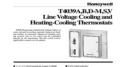
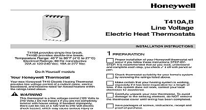
T4098A B Electric Heat Thermostats DATA Controls both fan forced and baseboard electric Temperature responsive vapor filled dual diaphragm element provides 2 cid 176 F 1 cid 176 C sensitivity with droop Replaces virtually all standard wall mounted line thermostats long lasting Micro Switch mechanism Color coded leads allow easy installation Protective cover door opens to provide access to knob Attractive sloped faceplate allows easy viewing of Classic styling 1 1 2 Information 2 3 and Adjustments 4 6 6 T4098A B Deluxe Electric Heat Thermostats provide high line voltage direct control of resistance rated heating equipment 1996 Honeywell Inc All Rights Reserved DELUXE ELECTRIC HEAT THERMOSTATS Specifications given in this publication do not normal manufacturing tolerances Therefore unit may not exactly match the listed Also this product is tested and under closely controlled conditions and minor differences in performance can be if those conditions are changed For exact specifications contact your Honeywell representative Models models are selected and packaged to provide of stocking and handling and also maximum value See Table 1 for TRADELINE model 1 Thermostat Specifications Switching Spst C to 90 to 30 Dpst to 90 to 30 line on line with knob OFF or or stops locking stops locking Ratings Noninductive Resistive Loads at 120 208 240 Vac 60 Hz at 277 Vac 60 Hz Connections in 150 mm leads suitable for connecting to aluminum if approved special service CO ALR connectors are Element dual diaphragm Adjustment knob on front of thermostat 1 cid 176 C nonadjustable Figs 1 and 2 directly on vertical 2 x 4 in outlet box or on 4 x 4 in box using ring adapter ordered separately XAPX Laboratories Listed File No E47434 Guide Standards Association Listed File No LR1322 Standards Association Performance Certified Range Stop and Locking Screw Assembly Includes cover screws Tinnerman clips wrench and range plastic pins to insert inside cover for field of minimum and maximum temperature settings purchasing replacement and modernization products from your TRADELINE wholesaler or distributor refer to the Catalog or price sheets for complete ordering number or specify INFORMATION Model number Switching Type of finish you have additional questions need further information or would like to comment on our products or services please write or Your local Honeywell Home and Building Control Sales Office check white pages of your phone directory Home and Building Control Customer Relations 1885 Douglas Drive North Minnesota 55422 4386 Canada Limited Honeywell Limit 35 Dynamic Drive Scarborough Ontario M1V 4Z9 International sales and offices in all principal cities of the world Manufacturing in Australia Canada Finland France Germany Japan Mexico Spain Taiwan United Kingdom U S A VIEW VIEW 67 DELUXE ELECTRIC HEAT THERMOSTATS Disconnect power supply to prevent electrical or equipment damage connecting with aluminum conductors use CO solderless wire connectors to avoid fire Do not remove thermostat cover until wiring is to avoid damaging the sensing element a vertical outlet box that is used to mount the about 5 ft 1.5m above the floor in an area with air circulation at room temperature 73 not install the thermostat where it may be affected by drafts or dead spots behind doors in corners or under 1 T4098 dimensions in in mm NOTICE this control is replacing a control that contains in a sealed tube do not place your old in the trash your local waste management authority for regarding recycling and the proper of an old control containing mercury in a tube hot air from convectors radiant heat from sun or appliances concealed pipes and chimneys unheated uncooled areas such as an outside wall the thermostat and Mounting Handle the thermostat with care to avoid the sensing element or control Use a separate limit control in the heating Installing this Product Read these instructions carefully Failure to follow these could damage the product or cause a condition Check the ratings on the product to make sure the is suitable for your application must be a trained experienced service After installation is complete check out product as provided in these instructions VOLTAGE CONTROL SHOCK HAZARD local codes and ordinances when installing this Improper handling can cause serious or death SUPPLY PROVIDE DISCONNECT MEANS AND OVERLOAD AS REQUIRED SPECIAL SERVICE CO ALR SOLDERLESS CONNECTORS CONNECTING ALUMINUM CONDUCTORS OR A FIRE MAY RESULT AND REMAKES BELOW 31 NORMALLY ACTIVATED BREAKS ON A TEMPERATURE RISE ON A TEMPERATURE FALL A SEPARATE LIMIT CONTROL IN THE HEATING APPLIANCE 2 Typical wiring connections for T4098A DELUXE ELECTRIC HEAT THERMOSTATS WIRE SUPPLY PROVIDE DISCONNECT MEANS AND OVERLOAD AS REQUIRED SPECIAL SERVICE CO ALR SOLDERLESS CONNECTORS CONNECTING ALUMINUM CONDUCTORS OR A FIRE MAY RESULT AND REMAKES BELOW 31 NORMALLY ACTIVATED BREAKS ON A TEMPERATURE RISE ON A TEMPERATURE FALL A SEPARATE LIMIT CONTROL IN THE HEATING APPLIANCE AT POSITIVE OFF ONLY NOT THERMALLY ACTIVATED NOT CONNECT GROUNDED CONDUCTORS NEUTRAL ON OR 277V CIRCUITS INSULATE AND TAPE OR CUT OFF WIRES IF UNUSED 3 Typical wiring connections for T4098B locking cover feature is desired insert the locking clip in the thermostat base before mounting thermostat on the wall See Fig 7 Applications Disconnect power to thermostat to prevent electrical or equipment damage All wiring must comply local electrical codes and ordinances Remove the old thermostat from the wall be careful not damage the wiring insulation Check the old wire insulation for cracks nicks or fraying approved electrical tape to insulate wires or wires as necessary Do not remove T4098 Thermostat Cover Using wire approved for No 12 wires make line connections directly to the leadwires on the See Figs 2 and 3 for typical wiring Prebend and push the solid wires into the outlet box While holding the thermostat base with one hand use other hand to remove the thermostat cover by the bottom cover edge and pulling outward from the the