Notifier 411UDAC-Option-Relays-Installation-Drawing

File Preview
Click below to download for free
Click below to download for free
File Data
| Name | notifier-411udac-option-relays-installation-drawing-1495037826.pdf |
|---|---|
| Type | |
| Size | 1011.12 KB |
| Downloads |
Text Preview
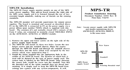
Fire Alarm Communicator Fire Alarm Communicator provides sockets for two relays P N 411RK rated for 2.0 amps 30 VDC Relay 1 must be installed in the main circuit socket labeled K6 and Relay 2 must be installed in the labeled K5 As a safety precaution it is highly recommended that all power be removed from the main circuit board before Installation Drawing 51128 Rev A1 10 31 03 ECN 03 742 Position the relay module so that the largest gap between the first set of pins and the second set is to the left as the optional relays in Figure 1 Carefully align the relay module pins with the socket holes making certain that the two pins on each end of relay line up with the two holes at each end of the socket Press the relay firmly into place being careful not to bend any of the pins Module pins gap Module 1 Relay Installation relays are programmable for activation on fire alarm host panel trouble fire supervisory process monitoring communication failure DACT trouble and security alarm Refer to Programming in the Fire Alarm manual Addresses 88 are used for programming relay functions and enable Relay connections may be power limited or nonpower limited provided that 0.25 spacing is between conductors of power limited and nonpower limited circuits 1 Shown Programmed for Alarm Super or any other function except DACT Host Panel Trouble and Process Moni contacts shown in deenergized condition power applied to Fire Alarm Communica 1 RELAY 2 2 Programmable Relay automatically change to energized condition programmed for Trouble 2 Shown Programmed for DACT Host Panel Trouble or Process Mon relay contacts shown in energized with power applied to Fire Alarm Document 51128 Rev A1 10 31 03 P N 51128 A1 of 1