Notifier Audio Fiber Link (AFL) Combination Guide
File Preview
Click below to download for free
Click below to download for free
File Data
| Name | notifier-audio-fiber-link-afl-combination-guide-9358760142.pdf |
|---|---|
| Type | |
| Size | 1.35 MB |
| Downloads |
Text Preview
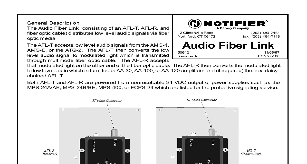
12 Clintonville Road CT 06472 Description Audio Fiber Link consisting of an AFL T AFL R and optic cable distributes low level audio signals via fiber media AFL T accepts low level audio signals from the AMG 1 or the ATG 2 The AFL T then converts the low audio signal to modulated light which is transmitted multimode fiber optic cable The AFL R accepts modulated light on the other end of the fiber optic cable The AFL R then converts the modulated light low level audio which in turn feeds AA 30 AA 100 or AA 120 amplifiers and if required the next daisy AFL T AFL T and AFL R are powered from nonresettable 24 VDC output of power supplies such as the MPS 24B BE MPS 400 or FCPS 24 which are listed for fire protective signaling service Fiber Link 484 7161 203 484 7118 97 160 A 1 AFL R AND AFL T ASSEMBLIES 50642 A 11 06 97 AFL T or AFL R may be mounted in a listed CHS 4 CHS 4L or an ABS 8R When mounting on a use the inner position When the AFL T or AFL R is mounted on the CHS 4 and CHS 4L ade clearance above the board is required Outer position mounting on the CHS 4 is possible only if the is mounted with components facing inward Mounting Position two 6 32 standoffs onto PEM studs in chassis Screw two 4 40 screws into top holes of board and two 4 40 standoffs Place tab on bottom of board into slot Screw boards into 6 32 standoffs with 6 32 screws refer to Figure 2 The top standoffs should rest on the back of the chassis Screws Standoffs 2 MOUNTING THE AFL T OR AFL R TO THE CHS 4 Outer Position board components must face inward Slip the board tab in the top slot of the CHS 4 with the facing the back of the chassis Rest the top of the board on the mounting tabs at the top the CHS 4 and attach using two 4 40 screws the two 4 40 standoffs on the top row of PEM studs on the CHS 4L Slide the board tab in the inner of the CHS 4L and rest on the standoffs Use the two 4 40 screws to attach the board to the chassis to Figure 3 Studs Screws 3 MOUNTING THE AFL T OR AFL R TO THE CHS 4L 50642 A 11 06 97 Mounting mounting the ABS 8R determine which knockouts are required to wire the AFL T or AFL R and the designated knockouts Mount the ABS 8R Place the AFL T or AFL R on the PEM standoffs the ABS 8R using four 4 40 screws refer to Figure 4 Draw appropriate wiring in through knockouts Screws Standoffs 4 MOUNTING THE AFL T OR AFL R TO THE ABS 8R Optic Link Refer to Figure 5 attenuation of fiber optic cabling between the AFL T or AFL R must not exceed a 10 dB limit At system design stage apply the following steps to establish the limit Find the maximum dB loss per foot within the cable manufacturer cid 146 s specifications Determine total attenuation between the two nodes repeaters due to the cable loss feet x length in feet Establish the dB loss for each connector and splice Sum all the losses Add the attenuation factors obtained in steps 1 and 2 for a total This will provide an approxi attenuation total actual attenuation can be measured end to end with standard fiber optic test equipment using a wavelength of 850 nanometers following are supported by Audio Fiber Link Connectors ST Style ST is a registered trademark of AT T Fiber Type Multimode Size 62.5 125 micrometers Wavelength 850 nanometers Maximum Attenuation of Fiber Optic Link Between AFL T and AFL R Cannot Exceed 10 dB 50642 A 11 06 97 Fiber Link may be used in systems where the use of wire media is not possible due to security requirements fiber optic cable is already installed and available for low level audio distribution significant distances between AMG 1 and remote amplifier cabinets dictate the use of fiber high intensity electromagnetic fields of audible frequencies could be coupled to wire type low level loop both distance and physical location of remote cabinets require the use of star topology to 50 AFL T transmitters may be connected to the output of an AMG 1 AMG E or ATG 2 low level audio maximum of ten amplifiers may be fed from the AFL R output and a maximum of ten AFL Ts may be fed a single AFL R The maximum series connection of audio fiber links is two AFL T R pairs deep the audio system installation is complete the audio gain level must be adjusted as follows Start with the AFL T connected directly to the low level audio source AMG 1 ATG 2 the AFL T Level LED If the Level LED is red or flashes red continuously while in it is indicating too high a signal level Connect one or more 470 ohm resistors in across the input One 470 ohm resistor is normally installed on the low level circuit The AFL T Level LED should indicate green at all times except during signal when it may momentarily flash red Adjust the gain on all amplifiers that are connected in parallel with the first AFL T Proceed to the AFL R terminating the first stage fiber optic link If the AFL R feeds a stage AFL T observe the Level LED Add one or two 470 ohm resistors in parallel the AFL R output if necessary to lower the signal level Adjust the gain on all amplifiers that are fed from the first stage AFL R Repeat step four for the amplifiers fed from the second stage AFL R Add parallel resis if necessary Test the entire system in systems normal and alarm checking each signal that will be to verify that the above requirements are satisfied and that there is no significant distortion A system requiring many fiber links may also require larger batteries and external charg The AFL T and the AFL R have operating currents of 104 mA and 51 mA respec and operate from 20.4 to 26.4 VDC Refer to fire panel instructions for battery AFL T should be powered by the 24 VDC U L listed power supply connected to the same battery negative as the audio signal source AMG ATG AFL R Class A low level audio riser cannot be implemented when using audio fiber link Any combination of up to 50 AFL T transmitters and AA 30 AA 100 and AA 120 series may be connected to the output of any one AMG or ATG All of the AFL T must remain in the same cabinet as the AMG or ATG 50642 A 11 06 97 5 AUDIO FIBER OPTIC LINK 6 CONNECTING THE AFL T TO THE AMG 1 AMG E 50642 A 11 06 97 7 CONNECTING AFL TS TO THE ATG 2 APPLICATION SHOWN 8 CONNECTING THE AFL R TO AMPLIFIERS AND SECOND STAGE AFL TS 50642 A 11 06 97 AFL T light emitting diode LED displays various intensities of green depending on the signal level high levels of audio signal will cause the LED to glow steady red indicating distortion AFL R LED displays various intensities of green depending on the level of optical power delivered the the optical signal level the dimmer the intensity of the LED The AFL R LED will glow steady red if link is not receiving enough light or if the fiber is disconnected is normal for bi color LEDs on both units to momentarily change from green to red during paging operation 50642 A 11 06 97 50642 A 11 06 97