Notifier LPX-751 Intelligent Laser Smoke Sensor (VIEW)

File Preview
Click below to download for free
Click below to download for free
File Data
| Name | notifier-lpx-751-intelligent-laser-smoke-sensor-view-9314206587.pdf |
|---|---|
| Type | |
| Size | 982.72 KB |
| Downloads |
Text Preview
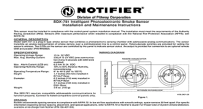
LASER SAFETY INFORMATION smoke detector does not produce any hazardous laser radiation and is certified as a Class 1 laser product under U S Department of Health and Human Services DHHS Radiation Performance Standard according to the Radiation for Health and Safety Act of 1968 radiation emitted inside the smoke detector is completely within the protective housings and external covers The beam cannot escape from the detector during any phase of operation Center of Devices and Radiological Health CDRH of the U S Food and Drug Administration implemented regula for laser products on August 2 1976 These regulations apply to laser products manufactured after August 1 1976 is mandatory for products marketed in the United States of controls adjustments or performance of procedures other than those specified in this manual may result in radiation exposure INTELLIGENT LASER SMOKE SENSOR INSTRUCTIONS installing this sensor please thoroughly read the System Smoke Detector Application Guide which provides information on detector spacing placement zoning wiring and special applications Copies of this manual are from Notifier This sensor must be installed in compliance with the control panel manufacturer installation man Sensors offer maximum performance when installed in compliance with National Fire Protection Association NFPA NFPA 72 This manual should be left with the owner user of this equipment This sensor must be tested and maintained regularly following NFPA 72 requirements It should be at least once a year DESCRIPTION LPX 751 is a plug in smoke sensor that combines a laser photoelectronic sensing chamber with addressable communications The use of a laser diode provides substantial improvements in signal to noise ratio compared a traditional LED light source The sensor transmits an analog representation of smoke density over a communication to a control panel Rotary decade switches are provided for setting the sensor address see figure 2 The sensor two multicolored LEDs controlled by the panel to indicate sensor status Flashing green indicates normal operation steady red indicates alarm prealarm or trouble An output is provided for connection to an optional remote LED Model RA400Z Voltage Range 15 to 32 VDC Peak Standby Current 230 24 VDC no communication Average Standby Current 330 one communication every 5 seconds with LED blink enabled Alarm Current LED on 6.5mA 24 VDC Humidity Range 10 to 93 Relative Humidity noncondensing Temperature Range 0 to 37.8 32 to 100 U S to 50 14 to 122 Europe 1.7 inches 43mm installed in B710LP base 6.1 inches 155mm installed in B710LP base 4.1 inches 104mm installed in B501 base 3.6 oz 102 g ANNUNCIATOR RETURN LOOP refer to insert for the Limitations of Fire Alarm Systems 4 I56 748 07R 2001 Notifier 1 I56 748 07R 12 Clintonville Rd Northford CT 06472 1653 203 484 7161 recommends spacing sensors in compliance with NFPA 72 In low air flow applications with smooth ceilings sensors 30 feet apart For specific information regarding sensor spacing placement and special applications to NFPA 72 or Notifier System Smoke Detector Application Guide available at no charge from Notifier INSTRUCTIONS wiring must be installed in compliance with the National Electric Code NEC applicable local codes and any spe requirements of the Authority Having Jurisdiction AHJ Proper wire gauges should be used The installation wires be color coded to limit wiring mistakes and ease system troubleshooting Improper connections will prevent a from responding properly in the event of a fire power from the communication line before installing sensors wiring must conform to applicable local codes ordinances and regulations Wire the sensor base supplied separately per the wiring diagram see figure Set the desired address on the sensor address switches Install the sensor in the sensor base Push the sensor into the base while turning clockwise to secure it in place After all sensors have been installed apply power to the control unit and activate communication line Test the sensor s as described in the TESTING section of this manual 5 5 2 Rotary Decade Switch covers provide limited protection against airborne dust particles during shipment Dust covers must be removed the sensors can sense smoke Remove sensors prior to heavy remodeling or construction testing notify the proper authorities that the system is undergoing maintenance and will be temporarily out of ser Also disable the system to prevent unwanted alarms All sensors must be tested after installation and periodically Testing methods must satisfy the Authority Having Jurisdiction AHJ Sensors offer maximum performance tested and maintained in compliance with NFPA 72 The sensor can be tested in the following ways Functional Magnet Test Model M02 04 01 sensor can be functionally tested using a test magnet The test magnet electronically simulates smoke the sensing chamber testing the sensor electronics and connections to the control panel Hold the test magnet in the magnet test area as shown see figure 3 The sensor should alarm the panel LEDs on the sensor are controlled by the panel to indicate sensor status Coded signals transmitted the panel can control LED color as well as to latch or latch Refer to the control manufacturer technical documentation for sensor LED status operation Smoke Entry Aerosol Generator Gemini 501 GEMINI model 501 aerosol generator can be used for smoke entry testing Set the generator to represent to 5 ft obscuration as described in the GEMINI 501 manual Using the bowl shaped applicator apply until the panel alarms Smoke entry can also be simulated from the Notifier control panel sensor that fails any of these tests should be cleaned as described under CLEANING and retested If the sensor fails cleaning it must be replaced and returned for repair testing is complete restore the system to normal operation and notify the proper authorities that the system is back E S T A G N E T 3 Test Magnet Position SENSITIVITY SETTING use of the 0.03 to 0.5 per foot sensitivity setting requires a 90 day test period to ensure that the detector is suitable for this setting The following steps must be followed to meet Notifier and UL requirements for high sensitivity application Each detector intended for 0.03 to 0.5 per foot alarm application shall have its initial alarm setting set for 0.5 per foot alarm level The initial prealarm setting for the detector shall be set to the intended alarm setting the system Prealarm shall be set for nonlatching operation Detectors set at 0.03 to 0.5 per foot are intended for use in smoke free environmentally controlled applications as computer rooms and clean rooms In order to determine if an environment is suitable for installation the shall be operated continuously for 90 days with all environmental factors including temperature humidity flow occupancy etc similar to the intended application for these detectors An electronic history file or printer be used to record all events associated with the detectors under testing At the end of 90 days the results of the test shall be inspected by an authorized Notifier representative or the end if trained by an authorized Notifier representative If no alarms or prealarms are recorded for the detectors under the system may be set to the tested prealarm level in the 0.03 to 0.5 per foot range The LPX 751 has been approved by LPCB at its least sensitive