Notifier MMX-1(A) Monitor Module CMX-2(A) Control Module And ISO-X

File Preview
Click below to download for free
Click below to download for free
File Data
| Name | notifier-mmx-1-a-monitor-module-cmx-2-a-control-module-and-iso-x-8921673045.pdf |
|---|---|
| Type | |
| Size | 1.04 MB |
| Downloads |
Text Preview
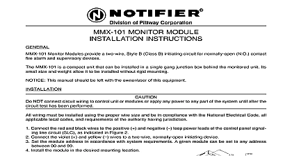
of Pittway Corporation MONITOR MODULE CMX 2 A CONTROL MODULE AND FAULT ISOLATOR MODULE INSTALLATION INSTRUCTIONS information is included as a quick reference installation guide Refer to the appropriate Notifier Installation Manual for system information If the modules will be installed in an existing operational system inform the operator and local that the system will be temporarily out of service Disconnect power to the control panel before installing the modules This manual should be left with the owner user of this equipment DESCRIPTION MONITOR MODULES provide a two wire or four wire fault tolerant circuit for normally open contact fire alarm and supervisory devices or normally open or normally closed security devices The LED indicator be latched on or returned to the normal mode by code command from the Rotary decade switches are used to set the address of each module CONTROL MODULES allow a compatible control panel to switch contacts by code command The control module offers a status LED can be latched on or returned to the normal mode by code command from panel Rotary decade switches are used to set the address of each module 5 5 LED DECADE SWITCHES TEST 1 Montior and Control Module control module offers two modes of switching operation As shipped the is configured for switching an external power source to notification ap The external power source can be a DC power supply or an audio amplifier up to 70.7 Vrms In this mode the mod reports supervision status of the connected loads to the control panel Load circuit status is reported as a NORMAL or SHORTED circuit Two pairs of output termination points are available for fault tolerant wiring The second mode of operation allows the panel to control one Form C set of contacts Circuit connections to the contacts are not super by the module This mode is enabled by breaking two external tabs on the module and Indicators FAULT ISOLATOR MODULES enable part of the communications loop to continue operating when a short circuit oc on it An LED indicator blinks in the normal condition and turns on during a short circuit condition The module will auto restore the entire communications loop to the normal condition when the short circuit is removed REQUIREMENTS insure proper operation these modules shall be connected to compatible Notifier system control panels only MMX 1 A CMX 2 A AND ISO X DEVICES CMX 2 A and ISO X modules mount directly to 4 inch square electri boxes as shown in Figure 2A The box must have a minimum depth of 21 8 All wiring must conform to applicable local codes ordinances and When using control modules in nonpower limited applica the CB500 Module Barrier must be used to meet UL require for the separation of power limited and nonpower limited termi and wiring The barrier must be inserted in a 4 x4 x21 8 junction and the control module must be placed into the barrier and at to the junction box Figure 2A The power limited wiring must placed into the isolated quadrant of the module barrier Figure 2B Install module wiring in accordance with the job drawings and appropriate diagrams Figures 3 10 Set the address on the module per job drawings Secure module to electrical box supplied by installer as shown in Figure 2A TEST monitor and control modules can be tested with a test magnet available Notifier M02 04 00 see Figure 1 The magnet test checks the module and connections to the control panel Interfaced initiating and indi devices must be tested independently 2B 2A Module with Barrier 12 Clintonville Rd Northford CT 06472 1610 203 484 7161 MONITOR MODULE WIRING DIAGRAMS PANEL OR DEVICE MODULES TO LISTED COMPATIBLE CONTROL PANELS ONLY LINE VDC MAX PAIR RECOMMENDED WIRING SHOWN IS SUPERVISED AND POWER LIMITED NEXT NUMBER OF UL LISTED CONTACT CLOSURE MAY BE USED DO NOT MIX FIRE INITIATING SUPERVISORY OR DEVICES ON THE SAME MODULE DEVICE CIRCUIT IDC NFPA STYLE B LIMITED 230 MAX 12 VDC MAX INSTALLATION WIRING SHALL NOT 40 OHMS OR 2500 FEET 12 18 AWG CONTACT CLOSURE DEVICES PER INSTALLATION INSTRUCTIONS NEXT NUMBER OF UL LISTED CONTACT CLOSURE MAY BE USED DO NOT MIX FIRE INITIATING SUPERVISORY OR DEVICES ON THE SAME MODULE K EOL RESISTOR INTERNAL AT 8 9 PANEL OR DEVICE MODULES TO LISTED COMPATIBLE NOTIFIER CONTROL PANELS ONLY LINE VDC MAX PAIR RECOMMENDED 3 TYPICAL 2 WIRE INITIATING CIRCUIT CONFIGURATION NFPA STYLE B WIRING SHOWN IS SUPERVISED AND POWER LIMITED DEVICE CIRCUIT IDC NFPA STYLE D LIMITED 230 MAX 12 VDC MAX INSTALLATION WIRING SHALL NOT 40 OHMS OR 2500 FEET 12 18 AWG CONTACT CLOSURE DEVICES PER INSTALLATION INSTRUCTIONS 4 TYPICAL 4 WIRE FAULT TOLERANT INITIATING CIRCUIT CONFIGURATION NFPA STYLE D CONTROL MODULE WIRING DIAGRAMS MODULES TO LISTED COMPATIBLE CONTROL PANELS ONLY PANEL OR DEVICE LINE VDC MAX PAIR RECOMMENDED VDC BRANCH CIRCUIT NOT LOOP WIRE ON TERMINALS 4 BREAK WIRE RUN TO PROVIDE OF CONNECTIONS REGULATED 24 VDC SUPPLY LISTED FOR FIRE WITH BATTERY BACKUP LOSS OF PRIMARY POWER EXTERNAL POWER SOURCE BE POWER LIMITED PER NFPA 70 INDICATING APPLIANCE OUTPUT OF OR AVPS 24 MAY BE USED INDICATING APPLIANCES THAT ARE FOR SERVICE WITH NOTIFIER AM2020 AFP1010 CONTROL PANELS WIRING SHOWN IS SUPERVISED AND POWER LIMITED NEXT LOAD APPLIANCE CIRCUIT IAC NFPA STYLE W UL LISTED INDICATING APPLIANCES A 30 VDC A 30 VDC 6 PF A 30 VDC 35 PF DUTY EOL LISTED EOL RELAY ENERGIZED VDC COIL 9 8 7 6 5 DO NOT TERMINAL 5 NEXT CONTROL MODULE OR END LINE RELAY EOLR ONE EOLR PER 24 VDC BRANCH CIRCUIT POLARITIES ARE IN ALARM 5 TYPICAL INDICATING CIRCUIT CONFIGURATION NFPA STYLE W MODULES TO LISTED COMPATIBLE CONTROL PANELS ONLY PANEL OR DEVICE VDC BRANCH CIRCUIT NOT LOOP WIRE ON TERMINALS 4 BREAK WIRE RUN TO PROVIDE OF CONNECTIONS REGULATED 24 VDC SUPPLY LISTED FOR FIRE WITH BATTERY BACKUP LOSS OF PRIMARY POWER EXTERNAL POWER SUPPLY BE POWER LIMITED PER NFPA 70 INDICATING APPLIANCE OUTPUT OF OR AVPS 24 MAY BE USED INDICATING APPLIANCES THAT ARE FOR SERVICE WITH NOTIFIER AM2020 AFP1010 CONTROL PANELS LINE VDC MAX PAIR RECOMMENDED 9 8 7 6 5 DO NOT TERMINAL 5 WIRING SHOWN IS SUPERVISED AND POWER LIMITED NEXT LOAD APPLIANCE CIRCUIT IAC NFPA STYLE X UL LISTED INDICATING APPLIANCES A 30 VDC A 30 VDC 6 PF A 30 VDC 35 PF DUTY RESISTOR INTERNAL AT 8 9 LISTED EOL RELAY ENERGIZED VDC COIL models have a resistive rating of 1.5A 30 VDC in this configuration POLARITIES ARE IN ALARM 6 TYPICAL FAULT TOLERANT INDICATING CIRCUIT CONFIGURATION NFPA STYLE X NEXT CONTROL MODULE OR END LINE RELAY EOLR ONE EOLR PER 24 VDC BRANCH CIRCUIT LINE VDC MAX TWISTED RECOMMENDED MODULES TO LISTED COMPATIBLE CONTROL PANELS ONLY PANEL OR