Notifier N-ANN-80-Character LCD

File Preview
Click below to download for free
Click below to download for free
File Data
| Name | notifier-n-ann-80-character-lcd-5649087321.pdf |
|---|---|
| Type | |
| Size | 691.98 KB |
| Downloads |
Text Preview
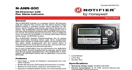
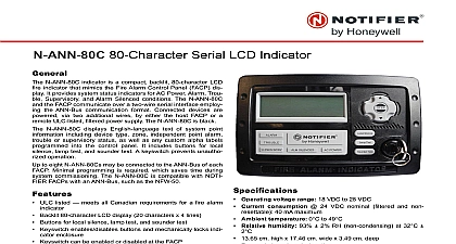
N ANN 80 LCD Annunciator N ANN 80 annunciator is a compact backlit 80 character fire annunciator that mimics the Fire Alarm Control Panel display It provides system status indicators for AC Alarm Trouble Supervisory and Alarm Silenced condi The N ANN 80 and the FACP communicate over a two serial interface employing the ANN BUS communication Connected devices are powered via two additional by either the host FACP or a remote UL listed filtered supply N ANN 80 is black for white order N ANN 80 W N ANN 80 displays English language text of system point including device type zone independent point trouble or supervisory status as well as any custom labels programmed into the control panel It includes con switches for remote control of critical system functions A prevents unauthorized operation of control to eight N ANN 80s may be connected to the ANN BUS of FACP Minimal programming is required which saves time system commissioning The N ANN 80 is compatible NOTIFIER FACPs with an ANN BUS such as the NFW 50 Listed to UL Standard 864 9th Edition Backlit 80 character LCD display 20 characters x 4 lines Mimics all display information from the host panel Control switches for System Acknowledge Signal Silence and Reset the FACP Control switches can be independently enabled or disabled Keyswitch enables disables control switches and mechani locks annunciator enclosure Keyswitch can be enabled or disabled at the FACP Enclosure supervised for tamper System status LEDs for AC Power Alarm Trouble Supervi and Alarm Silence Local sounder can be enabled or disabled at the FACP N ANN 80 connects to the ANN BUS terminal on the FACP requires minimal panel programming Displays device type identifiers individual point alarm trou supervisory zone and custom alpha labels Time and date display field Surface mount directly to wall or to single double or 4 electrical box Semi flush mount to single double or 4 square electrical Use ANN SB80KIT for angled view mounting Can be remotely located up to 6,000 feet 1,800 m from the Backlight turns off during AC loss to conserve battery power will turn back on if an alarm condition occurs May be powered by 24 VDC from the host FACP or by remote supply requires 24 VDC Up to eight N ANN 80s can be connected on the ANN BUS and Indicators AC Power Alarm A1 65 Trouble Supervisory Alarm Silenced Operating voltage range 18 VDC to 28 VDC Current consumption 24 VDC nominal filtered and non 40 mA maximum Ambient temperature 32 to 120 0 to 49 Relative humidity 93 2 RH noncondensing at 32 5.375 13.65 cm high x 6.875 17.46 cm wide x 1.375 2 90 3 cm deep For use indoors in a dry location All connections are power limited and supervised Listings and Approvals listings and approvals below apply to the N ANN 80 In cases certain modules may not be listed by certain agencies or listing may be in process Consult factory latest listing status UL S635 FM approved CSFM 7120 0028 240 MEA 442 06 E Vol 2 ANN BUS THE DEVICES ON THE ANN BUS FROM POWER SUPPLY ANN BUS can be powered by an auxiliary power supply the maximum number of ANN BUS devices exceeds the power requirements See the FACP manual for more 5 22 09 Page 1 of 2 DEVICE ADDRESSING ANN BUS device requires a unique address ID Number order to communicate with the FACP A maximum of 8 devices be connected to the FACP ANN BUS communication circuit the FACP manual for more information REQUIREMENTS COMMUNICATIONS CIRCUIT N ANN 80 connects to the FACP ANN BUS communica circuit To determine the type of wire and the maximum wir distance that can be used with FACP ANN BUS accessory it is necessary to calculate the total worst case current for all modules on a single 4 conductor bus The total worst current draw is calculated by adding the individual worst currents for each module For total worst case current draw on a single ANN BUS to appropriate FACP manual calculating the total worst case current draw the following specifies the maximum distance the modules can be from the FACP on a single wire run The table ensures volts of line drop maximum In general the wire length is lim by resistance but for heavier wire gauges capacitance is limiting factor cases are marked in the chart with an asterisk Maxi length can never be more than 6,000 feet 1,800 m of gauge used See table below REQUIREMENTS POWER CIRCUIT 14 to 18 AWG 0.75 2.08 mm2 wire for 24 VDC power cir is acceptable All connections are power limited and supervised A maximum of eight N ANN 80 modules may be connected this circuit Gauge Gauge Gauge Gauge Pair Wiring Distance FACP to Last ANN BUS Module Worst Case Draw amps max 6,000 ft ft ft ft ft ft ft ft ft ft ft ft ft ft ft ft ft ft ft ft ft ft ft ft ft ft ft ft ft ft ft ft ft ft ft ft ft ft ft ft CONFIGURATION following figure illustrates the wiring between the FACP and devices and power are supervised power limited OPTIONS Black 80 character LCD Annunciator White 80 character LCD Annunciator Black surface mount backbox with angled White surface mount backbox with angled Device Wiring to ANN BUS Device by Honeywell International Inc All rights reserved Unauthorized use this document is strictly prohibited document is not intended to be used for installation purposes We try to keep our product information up to date and accurate cannot cover all specific applications or anticipate all requirements specifications are subject to change without notice more information contact Notifier Phone 203 484 7161 FAX 203 484 7118 in the U S A 2 of 2 dn 7114 c 5 22 09