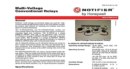
Notifier PAM-1, PAM-2, and PAM-4 Multi-Voltage Relay Modules

File Preview
Click below to download for free
Click below to download for free
File Data
| Name | notifier-pam-1-pam-2-and-pam-4-multi-voltage-relay-modules-7362810954.pdf |
|---|---|
| Type | |
| Size | 865.96 KB |
| Downloads |
Text Preview
PAM 1 PAM 2 and PAM 4 Relay Modules Products Controls Inc PAM 1 PAM 2 and PAM 4 Multi Relay Modules are encapsulated multi voltage The PAM 1 relay provides 10.0 Amp Form C contacts may be energized by one of three input voltages 24 VAC VDC or 115 VAC The PAM 2 relay provides 7.0 Amp contacts and may be energized by one of two input 12 VDC or 24 VDC The PAM 4 relay provides 10.0 Form C contacts and may be energized by a wide voltage from 9 VDC to 40 VDC red LED is provided on both models When illuminated it the relay coil is energized model may be mounted by using the double sided adhe tape the self drilling screw or by placing loosely in a PAM 2 and PAM 4 Relay Modules are ideal for appli where remote relays are required for control or status They are suitable for use with HVAC temperature fire alarm security energy management and lighting systems requirements PAM 1 0.015 Amps per position 24 VDC 24 VAC 115 PAM 2 0.015 Amps per position 12 VDC or 24 VDC PAM 4 0.015 Amps per position 24 VDC or 12 VDC UL recognized SPDT Rating PAM 1 10.0 A 115 VAC 7.0 A 28 VDC 250uA 5 PAM 2 7.0 A 115 VAC 7.0 A 28 VDC 250uA 5 PAM 4 10.0 A 120 VAC 7.0 A 24 VDC 250uA 5 Temperature Range 58 to 185 50 to 1.5 3.81 cm high x 1.0 2.54 cm wide x 2.223 cm deep with 12 30.48 cm wire leads 18 0.75 mm2 Listings and Approvals listings and approvals apply to the modules specified in document In some cases certain modules or applications not be listed by certain approval agencies or listing may in process Consult factory for latest listing status UL Listed S3403 MEA 73 92 E Volume XXI CSFM 7300 1004 101 Line Information Single SPDT relay with LED double sided adhesive mounting screw 12 30.48 cm leads and six wire nuts Single SPDT relay with LED double sided adhesive mounting screw 12 30.48 cm leads and six wire nuts Single SPDT relay with LED double sided adhesive mounting screw 12 30.48 cm leads and six wire nuts 08 19 14 Page 1 of 2 Diagrams by Honeywell International Inc All rights reserved Unauthorized use this document is strictly prohibited document is not intended to be used for installation purposes We try to keep our product information up to date and accurate cannot cover all specific applications or anticipate all requirements specifications are subject to change without notice more information contact Notifier Phone 203 484 7161 FAX 203 484 7118 2 of 2 DN 6755 A 08 19 14


