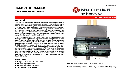
Notifier SD-651 & SD-651A Low Profie Plug-in Smoke Detectors

File Preview
Click below to download for free
Click below to download for free
File Data
| Name | notifier-sd-651-sd-651a-low-profie-plug-in-smoke-detectors-5190863472.pdf |
|---|---|
| Type | |
| Size | 972.00 KB |
| Downloads |
Text Preview
SD 651 Low Profile Photoelectronic Plug in Smoke Detector and Maintenance Instructions installing detectors please thoroughly read System Smoke Detector Application Guide which provides detailed information on detector spacing zoning wiring and special applications Copies of this manual are available from Notifier DESCRIPTION Model SD 651 low profile photoelectronic detector uses a state of the art optical sensing chamber This detector is designed to provide open area and to be used with compatible UL listed control panels only The capability of plugging this detector into a variety of special bases makes it versatile than equivalent direct wired models LEDs on the detector light to provide a local 360 visible alarm indication They flash every 10 seconds to indicate power is applied and the detector working properly The LEDs latch on in alarm Remote LED annunciator capability is standard and may be implemented through an optional accessory The alarm can be reset only by a momentary power interruption This detector may be tested by activating the internal reed switch with a mag Temperature Range Humidity Range Alarm inches 43 mm inches 101 mm oz 102 g to 60 14 to 140 Do not install in locations where normal ambient temperature range extends beyond to 49 32 to 120 to 93 Relative Humidity noncondensing by momentary power interruption SELECTION AND WIRING GUIDE to the installation instructions for the Plug in Detector Bases for base selection and wiring instructions Notifier has a variety of detector bases avail for this smoke detector including 2 wire applications with and without relays 4 wire and 120VAC applications bases are provided with screw terminals for power ground remote annunciator connections and relay contact connections if applicable The electrical for each detector base combination are also included in the base installation instructions All wiring must conform to applicable local codes ordinances and regulations Verify that all detector bases are installed that the initiating device circuits have been tested and that the wiring is correct Refer to detector manual for testing procedure power from initiating device circuits before installing detectors Install detectors a Place the detector into the detector base b Turn the detector clockwise until the detector drops into place c Continue turning detector clockwise to lock it in place Tamper Resistance The detector bases can be made tamper resistant When capability is enabled detectors cannot removed from the base without use of a tool See the detector base installation manual of the detector base for details in using this capability After all detectors have been installed apply power to the control unit Test the detector using the magnet as described under TESTING Reset the detector at the system control panel Notify the proper authorities that the system is back on line covers can be used to help limit dust entry into the smoke detector but they are not a substitute for removing the detector during building construction any dust covers before placing the system in service 1 I56 651 08R Notifier 12 Clintonville Rd Northford CT 06472 1652 203 484 7161 testing notify the proper authorities that the smoke detector system is under maintenance and will temporarily be out of service Disable the zone or system maintenance to prevent unwanted alarms Detectors must be tested after and as part of periodic maintenance the SD 651 as follows Before testing the detector check to ensure the LEDs blink If they do not detector has lost power check the wiring or it is defective return it for Test Magnet Model no M02 04 01 1 Place the magnet against the cover in the location designated by the raised to activate the test feature see Figure 1 2 The LEDs should latch ON within 5 seconds indicating alarm and annunciating panel Test Module MOD400R Use the MOD400R with a DMM or voltmeter to check the detector sensitivity as in the MOD400R manual Aerosol Generator Gemini 501 Set the generator to represent 4 to 5 Ft obscuration as described in the Gem 501 Manual Using the bowl shaped applicator apply aerosol until unit alarms the proper authorities that the system is back on line Detectors that fail these should be cleaned as described under MAINTENANCE and retested If the de still fail these tests they should be returned for repair is recommended that the detector be removed from its mounting base to facilitate The detector is cleaned as follows Before removing the detector notify the proper authorities that the smoke system is undergoing maintenance and will be temporarily out of Disable the zone or system undergoing maintenance to prevent alarms Remove the detector cover by prying away the four side tabs with a small bladed and then pulling the cover from the base Vacuum the screen carefully without removing it If further cleaning is required with Step 3 otherwise skip to Step 8 Remove the screen assembly by pulling it straight out see Figure 2 Remove the sensing chamber cover by pulling it straight out Clean the vaned chamber piece by vacuuming or blowing out dust and particles Replace the sensing chamber cover aligning the arrow on the top with arrow on To replace the screen place it over the chamber assembly turning it until it snaps printed circuit board place Replace the cover using the test module socket and LEDs to align the cover and gently pushing it until it locks into place Reinstall the detector the detector as described in TESTING Reconnect disabled circuits the proper authorities that the system is back on line 1 Bottom and side views showing of test magnet 2 refer to insert for the Limitations of Fire Alarm Systems 2 Notifier