Notifier SFP-5UD SFP-10UD(E) Five Zone Fire Alarm Control Panel Ten Zone Fire Alarm Control Panel

File Preview
Click below to download for free
Click below to download for free
File Data
| Name | notifier-sfp-5ud-sfp-10ud-e-five-zone-fire-alarm-control-panel-ten-zone-fire-alarm-control-panel-4016972358.pdf |
|---|---|
| Type | |
| Size | 707.78 KB |
| Downloads |
Text Preview
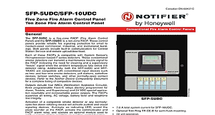
SFP 5UD SFP 10UD E Zone Fire Alarm Control Panel Zone Fire Alarm Control Panel SFP 5UD is a five zone FACP Fire Alarm Control Panel the SFP 10UD E is a ten zone FACP These control pan provide reliable fire signaling protection for small to commercial industrial and institutional build Both panels include built in communicators for Central Service and remote upload download of these FACPs is compatible with System Sensor i3 series detectors These conventional detectors can transmit a maintenance trouble signal to FACP indicating the need for cleaning and a supervisory signal when the ambient temperature falls below the rating Additionally both the SFP 5UD and SFP are compatible with conventional input devices such as and four wire smoke detectors pull stations waterflow tamper switches and other normally open contact Refer to the Notifier Device Compatibility Document a complete listing of compatible devices include four NACs Notification Appliance Circuits programmable Form C relays factory programmed for Trouble and Supervisory and 24 VDC special applica resettable and nonresettable power outputs The FACPs all wiring AC voltage battery level and telephone integrity of a compatible smoke detector or any normally fire alarm initiating device will activate audible and visual devices illuminate an indicating LED sound the sounder at the FACP activate the communicator and alarm relay and operate an optional module used to a remote station or initiate an auxiliary control function FireWatch Series internet monitoring modules IPDACT 2 IPDACT 2UD permit monitoring of alarm signals over the saving the monthly cost of two telephone lines not required the secondary telephone line may be providing backup communication over the public telephone line The SFP 10UDE offers the same features as the SFP but allows connection to 240 VAC Unless otherwise speci the information in this data sheet applies to both the 120 VAC the 240 VAC versions of these panels For ULC listed models see dn 60437 Listed to UL Standard 864 9th edition Built in DACT Digital Alarm Communicator Transmitter Style B Class B IDC Initiating Device Circuit SFP 5UD five IDCs SFP 10UD ten IDCs application power SFP 5UD four NACs SFP 10UD four NACs Silence Inhibit Auto Silence Fire Alarm Control Panels Strobe Synchronization for System Sensor Wheelock Faraday or Amseco devices Selective Silence horn strobe mute Temporal or Steady Signal Silenceable or Nonsilenceable Optional N CAC 5X Style Z Class A Converter Module for and IDCs 2 required for SFP 10UD Form C Relays for Alarm Trouble and Supervisory Con Ratings 2.0 A 30 VDC or 30 VAC resistive 3.0 A total system current for SFP 5UD 7.0 A total system current for SFP 10UD Optional Dress Panel DP 51050 red Optional Dress Panel DP 51050B black Optional Trim Ring TR CE B for semi flush mounting 24 volt operation Low AC voltage sense Alarm Verification PAS Positive Alarm Sequence Automatic battery trickle charger Up to eight ANN BUS annunciators Optional 8 zone Relay Module N ANN RLY Optional LED Annunciator Module N ANN LED Optional Remote LCD Annunciator N ANN 80 Optional Remote Printer Gateway N ANN S PG Optional LED Annunciator Driver N ANN I O transmitter AND SOFTWARE Can be programmed at the panel with no special software Programmable Make Break Ratio Upload Download local or remote of program and data via DACT 05 12 2009 Page 1 of 4 Style Y Class B NAC Notification Appliance Circuit spe Optional 4XTM module conventional reverse polarity city Notification Appliances may be programmed as additional equipment INTERFACE Built in DACT Digital Alarm Communicator Transmitter 80 character LCD display with backlighting and Real time clock calendar with automatic daylight savings ANN BUS for connection to remote annunciators Audible or silent walk test capabilities Piezo sounder for alarm trouble and supervisory and Indicators INDICATORS FIRE ALARM red SUPERVISORY yellow TROUBLE yellow AC POWER green ALARM SILENCED yellow BUTTONS ACKNOWLEDGE ALARM SILENCE SYSTEM RESET lamp test DRILL Blocks Power TB1 SFP 5UD FLPS 3 Power Supply 120 VAC 50 60 HZ A A A SFP 10UD FLPS 7 Power Supply 120 VAC 50 60 Hz SFP 10UDE FLPS 7 Power Supply 240 VAC 50 HZ size minimum 14 AWG 2.00 mm with 600 V insulation nonpower limited sealed lead acid only J12 Maximum Charging Circuit Normal Flat Charge 27.6 VDC 1.4 A Supervised nonpower limited Maximum Charger Capacity 18 AH battery for SFP 5UD 26 AH battery for SFP 10UD E Two 18 Ah batteries be housed in the FACP cabinet Larger batteries separate battery box such as the BB 26 or NFS Minimum Battery Size 7 AH Measurements 2 of 4 dn 60185 d 05 12 2009 Device Circuits TB4 and TB 6 on SFP 10UD Alarm Zones 1 5 on TB 4 SFP 5UD and SFP 10UD Alarm Zones 6 10 on TB6 SFP 10UD only Supervised and power limited circuitry Operation All zones Style B Class B Normal Operating Voltage Nominal 20 VDC Alarm Current 15 mA minimum Short Circuit Current 40 mA max Maximum Loop Resistance 100 ohms End of Line Resistor 4.7K ohm 1 2 watt P N 71252 UL Standby Current 2 mA to the Notifier Device Compatibility Document for listed devices Appliance Circuits TB5 and TB 7 on SFP only Four NACs Operation Style Y Class B Special Application power Supervised and power limited circuitry Normal Operating Voltage Nominal 24 VDC Maximum Signaling Current 3.0 A for SFP 5UD 2.5 A per NAC 7.0 A for SFP 10UD E 3.0 A maxi per NAC End of Line Resistor 4.7K ohm 1 2 watt Part 71252 Max Wiring Voltage Drop 2 VDC to the Notifier Device Compatibility Document for com listed devices C Relays TB8 Relay 1 factory default programmed as Alarm Relay Relay 2 factory default programmed as fail safe Trouble Relay 3 factory default programmed as Supervisory Relay Application Resettable Power TB9 Jumper selectable by JP31 for resettable or nonresettable Operating voltage 24 VDC nominal Maximum available current 500 mA appropriate for pow four wire smoke detectors Power limited circuit to the Notifier Device Compatibility Document for listed devices Sync Output TB2 Remote power supply synchro output only required for the SFP 5UD 24 VDC nomi special application power Maximum current is 40 mA Resistor 4.7K ohm Supervised and power lim circuit Line Information Five zone 24 volt Fire Alarm Control Panel black backbox FLPS 3 power supply technical man and a frame post operating instruction sheet Same as above in a red backbox Ten zone 24 volt Fire Alarm Control Panel black backbox FLPS 7 power supply technical man and a frame post operating instruction sheet Same as above with 220 VAC FLPS 7 Same as SFP 10UD in a red backbox Monitoring Module in bottom of enclosure with optional mounting kit PN Connects to primary and secondary DACT tele output ports for internet communications over customer ethernet internet connection Requires compa