Potter InstallationManual SPKSTR-24WLP-CSPKSTR-24

File Preview
Click below to download for free
Click below to download for free
File Data
| Name | potter-installationmanual-spkstr-24wlp-cspkstr-24-2843157960.pdf |
|---|---|
| Type | |
| Size | 1.36 MB |
| Downloads |
Text Preview
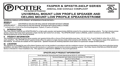
SPKSTR 24WLP SERIES AND CSPKSTR B AL CSPKSTR G AL CSPKSTR 24 AL WP CSPKSTR G AL WP AND MOUNT MOUNT SPEAKER WITH SELECTABLE STROBE MOUNT SPEAKER WITH SELECTABLE STROBE ALERT TEXT MOUNT SPEAKER WITH FIXED 15 75 CANDELA STROBE AMBER LENS ALERT TEXT MOUNT SPEAKER WITH FIXED 15 75 CANDELA STROBE BLUE LENS ALERT TEXT MOUNT SPEAKER WITH FIXED 15 75 CANDELA STROBE GREEN LENS ALERT TEXT MOUNT SPEAKER WITH FIXED 15 75 CANDELA STROBE RED LENS ALERT TEXT WALL MOUNT SPEAKER WITH FIXED 15 75 CANDELA STROBE AMBER LENS ALERT TEXT WALL MOUNT SPEAKER WITH FIXED 15 75 CANDELA STROBE BLUE LENS ALERT TEXT WALL MOUNT SPEAKER WITH FIXED 15 75 CANDELA STROBE GREEN LENS ALERT TEXT WALL MOUNT SPEAKER WITH FIXED 15 75 CANDELA STROBE RED LENS ALERT TEXT CAN ULC LISTED PRODUCT INFORMATION IS FOUND ON PAGE 4 Includes one or more of the following designators P plain no text R red or W white INTRODUCTION Potter Electric SPKSTR and CSPKSTR Series is a high quality speaker strobe The high intensity strobe utilizes a Xenon flash tube that generates a high intensity flash visible from all angles SPKSTR 24WLP and SPKSTR 24 AL is provided with a turn dial which allows for candela selection at the installation site 15Cd 30Cd 60Cd 75Cd or 110Cd The CSPKSTR 24 AL CSPKSTR G AL CSPKSTR R AL CSPKSTR 24 AL WP CSPKSTR B AL WP CSPKSTR G AL WP CSPKSTR R AL WP are fixed candela units available in 15 75 candela only This appliance is ideal for any occupancy that requires notification appliances per the applicable building or fire code or wherever dependable alarms are required SPKSTR 24WLP and SPKSTR 24 AL speaker strobe strobe is listed in compliance with ANSI UL 1971 Signaling Appliances for the Hearing Impaired The CSPKSTR 24 AL CSPKSTR B AL CSPKSTR R AL CSPKSTR 24 AL WP CSPKSTR B AL WP CSPKSTR G AL WP CSPKSTR R AL WP strobe is listed in compliance with ANSI UL 1638 Visual Signaling Private Mode Emergency and General Signaling PRODUCT INFORMATION SPKSTR and CSPKSTR Series Series speaker strobe offer a choice of field selectable power taps 1 8 1 4 1 2 1 2 and 4 Watts for use with either 25VRMS or 70.7VRMS audio amplifiers frequency range of the speakers is 400 4000Hz All devices are suitable for line supervision Speaker includes DC blocking capacitor which allows for supervision voltage of either polarity LOCATION appliance is intended for use in Fire Alarm Systems and is to be installed in accordance with this manual the recommendation of the local authorities having jurisdiction and other NFPA that provide standards on notification appliances for protective signaling systems The SPKSTR 24WLP SPKSTR 24 AL CSPKSTR 24 AL CSPKSTR B AL CSPKSTR G AL are intended for indoor installations only this appliance is not listed for outdoor or drip proof applications The CSPKSTR 24 AL WP CSPKSTR B AL WP CSPKSTR G AL WP are intended for indoor or outdoor installations this appliance is listed for outdoor or drip proof applications when used in conjunction with the SPKRBB back box AND SPKSTR 24 AL PRODUCT INFORMATION signal must be installed within 16 feet of the pillow when used in a sleeping area signal must be in the direct viewing area of the occupant in order to be seen signal can not be seen when objects such as doors furniture or walls block visual signal VISUAL SIGNALS FOR THE HEARING IMPAIRED ARE ONLY ONE METHOD OF ALERTING THE HEARING VISUAL SIGNALS MAY NOT BE THE PREFERRED METHOD FOR NOTIFYING ALL HEARING IMPAIRED THE VISUAL SIGNAL MUST BE SEEN BY THE SLEEPING PERSON IF THE PERSON HAS HEAD TURNED OR UNABLE TO BE ALERTED BY VISUAL THE VISUAL SIGNAL WILL NOT BE EFFECTIVE Signal should NEVER be relied upon as the primary fire alert for the hearing impaired under these common sense conditions Sleeping face down on the bedding or pillow Use of sleep medications of any kind Use of alcoholic beverages or recreational drugs Use of eye shades If there are tendencies of deep sleep conditions If a fire cuts power to AC circuits the visual signal will not operate If person is not within line of sight of visual signals these and other similar common situations an alternate fire alert method such as a non hearing impaired attendant is needed The visual signal only increases the chance of being alerted the presence of fire No system of this type can fully protect the hearing impaired in case of fire 1 CSPKSTR B AL CSPKSTR G AL CSPKSTR R AL CSPKSTR 24 AL WP CPKSTR B AL WP AND CSPKSTR R AL WP PRODUCT INFORMATION Spacing for Wall Mounted Visible Appliances per NFPA 72 2013 Edition Room Size Required Light Output Effective Intensity Cd Lights per Room Light per Wall Light Room x 6.10 x 8.53 x 9.14 x 12.2 x 13.7 x 15.2 x 16.5 x 16.8 x 18.3 x 19.2 x 20.7 x 21.3 x 24.4 x 27.4 x 30.5 x 33.5 x 36.6 x 39.6 x 20 x 28 x 30 x 40 x 45 x 50 x 54 x 55 x 60 x 63 x 68 x 70 x 80 x 90 x 100 x 110 x 120 x 130 Not allowable ELECTRICAL SPECIFICATIONS Lens Strobe Current Ratings with SPKSTR 24 and SPKSTR 24 AL Products 24VDC Max Current mA 24VFWR Max Current mA Intensity Requirements for Sleeping Areas Notification Appliance from Ceiling to Top of Lens than or equal to 24 than 24 CSPKSTR 24 AL WP CSPKSTR B AL WP CSPKSTR G AL WP CSPKSTR R AL WP Lens Lens Strobe Current Ratings 15 75 Candela Strobe with CSPKSTR 24 AL CSPKSTR 24 AL WP CSPKSTR B AL CSPKSTR B AL WP CSPKSTR G AL WP CSPKSTR R AL and CSPKSTR R AL WP Products 24VDC Max Current mA 24VFWR Max Current mA SPKSTR 15 75 AL SPKSTR 24WLP WP CSPKSTR 24 AL CSPKSTR 24 AL WP CSPKSTR B AL WP CSPKSTR G AL CSPKSTR G AL WP CSPKSTR R AL CSPKSTR R AL WP has a fixed candela rating of 15 75 per ANSI UL 1638 DC VOLTAGE RANGE LIMITS 16 33V FWR VOLTAGE RANGE LIMITS 16 33V THIS WAS ONLY TESTED TO THE STATED VOLTAGE RANGE S DO NOT APPLY 80 110 OF THIS RANGE FOR SYSTEM OPERATION Selectable Power Tap Selection Reverberant dBA 10ft Volts Volts Watt Watt Watt Watt Watt Watt CONSIDERATIONS To select the proper wattage input for the speaker move the jumper to the appropriate pin Always maintain electrical isolation between speaker and strobe wiring on combination units Do not exceed 130 of rated speaker voltage If excessive distortion is heard check amplifier for signal clipping If clipping exists reduce either amplifier input or gain Four screws are provided two for securing speaker to the back box and two for aesthetics The two non functional screws will be held in place by the pressure fit of the faceplate 2 ALL STROBES ARE DESIGNED TO AS SPECIFIED WITH CONTINUOUS VOLTAGE THIS APPLIANCE IS NOT FOR USE ON CODED OR SIGNALING CIRCUITS HOWEVER USE THE AVSM CONTROL MODULE IS PERMITTED SYNCHRONIZE THE STROBE REFERENCE AVSM CONTROL MODULE 550 0598 DATED 2 1 13 FOR MODULE WIRING AVSM MANUAL CAN BE OBTAINED CALLING POTTER ELECTRIC SIGNAL AT 1 800 325 3936 WHEN INSTALLING ROUTE FIELD AWAY FROM SHARP PROJECTIONS AND INTERNAL COMPONENTS DO NOT USE LOOPED WIRE UNDER BREAK WIRE RUN TO PROVIDE OF CONNECTION use with SPKSTR 24WLP CSPKSTR R AL product WIRE DISTANCE IN FEET VOLTAGE DEVICE MINIMUM VOLTAGE CURRENT DRAW WIRE CONDUCTIVITY STROBE ONLY INCLUDES WIRE TO AND FROM APPLIA