Potter PAD100-RB Addressable Relay Base

File Preview
Click below to download for free
Click below to download for free
File Data
| Name | potter-pad100-rb-addressable-relay-base-5360971482.pdf |
|---|---|
| Type | |
| Size | 1.29 MB |
| Downloads |
Text Preview
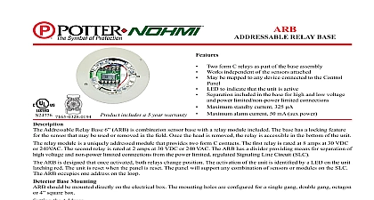
Features One form C relay as part of the base assembly Relay rating 2a 30VDC 0.5a 125VaC Works independent of the sensors attached May be mapped to any device connected to the Control panel LeD to indicate that the unit is active Separation included in the base for high and low voltage and limited non power limited connections Terminals accept 22 to 12 aWg wire sizes Supports Class a Class X and Class B wiring Does not require SLC Loop address product includes a 5 year warranty UUKL Listed for Smoke Control addressable Relay Base 6 paD100 RB is combination sensor with a relay module included The base has a locking feature for sensor that may be used or removed in the field Once the head is the relay is accessible in the bottom of the unit paD100 RB provides one form C relay output The relay is rated 2a 30 VDC and 0.5a at 125VaC The paD100 RB provides separation of high voltage and non power limited connections from power limited Signaling Line Circuit SLC The paD100 RB not consume an SLC address and does not require an auxiliary source VDC LeD form C N C COM N O 30VDC 0.5a 125VaC to 120 0 to 49 to 93 Non condensing Specifications Range for SLC Indicator Output Style Rating temperature relative range number of per zone without White 0.75 in 19mm 6.3 in 166 mm page 1 OF 2 Relay Base 8830103 REV C 12 18Potter Electric Signal Company LLC St Louis MO Phone 800 325 3936 www pottersignal comfirealarmresources com Base Mounting should be mounted directly on the electrical box The holes are configured for a single gang double gang octagon 4 square box See Fig 1 1 the two included attached the base to detector Features of Detector Head from Base To remove the detector from the base once the locking feature has activated insert a small screwdriver into the slot on the base to the plastic tab while simultaneously turning the detector head See Fig 3 3 small screwdriver slot to remove from base To remove the base cover from the lower enclosure once the locking has been activated insert a small screwdriver into the slot on on the base to push the plastic tab while simultaneously turning the head counter clockwise Information Relay Base No Feature the Locking Feature include a locking feature that prevents removal of the and removal of the base cover without using a tool To eliminate this feature break off the locking tab and then install detector See Fig 2 2 the detector to the back box the mounting off tab gray in image to disable feature page 2 OF 2 REV C 12 18Potter Electric Signal Company LLC St Louis MO Phone 800 325 3936 www pottersignal comPAD100 RBAddressable Relay Base firealarmresources com