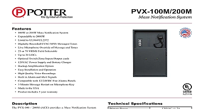
Potter PVX 100M Mass Notification System

File Preview
Click below to download for free
Click below to download for free
File Data
| Name | potter-pvx-100m-mass-notification-system-3568197042.pdf |
|---|---|
| Type | |
| Size | 1003.41 KB |
| Downloads |
Text Preview
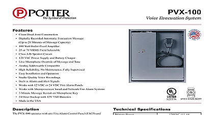
PVX 100M Notification System PVX 100M Mass Notification System is functionally identical to the PVX 100 with the exception of an Intelligent Interface for an LOC PVX 100M may be used as an ACU and combined with accessory modules to meet the requirements of UL2572 The system system a Physical and Communication Security Level 1 Audit Control Level 2 Stored Data and Access Control Security Level 0 per UL Mass Notification Standard The system is designed to be used in conjunction with a UL listed Fire Alarm Control Panel FACP to a Listed Voice Evacuation Alarm System with Mass Notification capabilities FACP provides all Fire initiating circuitry and a signaling circuit to the PVX 100M The PVX 100M provides its own internal as well as supervision for its speaker lines and accessories Any fault is reported back to the FACP In normal standby the circuit from the panel is connected to a matching EOLR Should the PVX 100M suffer an internal failure or should there be any on the speaker line or accessory a contact would open and the FACP would report it as an open fault for that circuit PVX 100M is designed to be powered from 120 VAC at 60 Hz and will provide 100W of audio Speakers may be 25 or 70 Vrms jumper 25V is factory set See Installation Instruction P N PVX 25 50 100 R2.14 for all Electrical Specifications Standard Terminal and Wiring Diagrams The PVC 100M is a complete Voice Evac MNS Module it is complete with built in tones and messages for Fire and MNS The may be coupled with additional PVC 100E Expander modules for systems requiring greater power PVX 100M and PVX 200M are complete Voice Evacuation Panels Where greater Audio power is required they meay be combined with panels PVX 100E 200E 300E 400E 500E 600E When using any EVX Expander Module refer to installation instructions P N 1 R2.14 100M 200M 1 PVC 100M 1 PVC 100M 1 PVC 100E Speaker Circuits Speaker Circuits other terminals are identical to the PVC 100 Module refer to P N 1 5001 R2.14 for full installation and ratings 2 4 6 Neg PVC RMI 1 24VDC 0.5A Audio Audio RS 485 RS 485 7 No Connection I2C Port Pin Connector Network Detail FACTORY DEFAULT SWITCH SETTINGS SN1 OFF Temporal Whoop Signal X Do not use X Do not use Fault Code Lock X Do not use AC Fault Delay ON Battery connected ON Mic connected OFF 8 sec initial delay ON OFF ON 8 sec repeat delay OFF ON Message On OFF 3 Repeats ON All Switch settings refer to Fire Tone Message only MNS Tone Messages must be Pre Configured for System Tone Messages will play continuous until reset 1 5001M R3.14 technical assistance please call Phantom Dr St Louis Missouri 63042 2 3 25V 1 3 3 connection from PVC 100M PVC SL8 and PVC RM8 LEDs On the Switch LED card which may be utilized with the PVC 100M or the PVC RMI Page Switch LEDs will steady Red for Paging flashing Red for Alarm MNS will indicate Green on any associated Zone Any Zone in will indicate Amber used for Message activation will indicate Red for Alarm or for MNS Messages used for Output activation will indicate Red inputs may also be used for MNS Message activation or Contact device must be Listed to UL2572 UL2017 must be in the same room within 20 and piped to PVX 100M cabinet 24VDC Neg conductors pairs AWG min Pair to PVC RM8 PVC RMI SL8 combinations to Installation Instruction PVC RMI R11.13 full installation and ratings GUIDE WIRE Ohms WIRE WIRE for 24 VDC pair must be sized to insure no more than a 20 drop in voltage at the last device Rev B additional units other devices maximum of 16 devices on any I2C Port required the PVX 100M may use a PVC ZM for separate speaker These may be activated All Call or by manual selection utilizing PVC SL8 Default operation is All Call on any Alarm MNS Event Switch or Contacts may also be employed Any external input must be Listed to UL2572 UL2017 must be in the same room within 20 and piped to PVX 100M cabinet to Installation Instructions P N 1 5022 E2.14 for full installation and ratings Notification Operational Guidelines PVX 100M is capable of operating In conjunction with a FACP or stand alone for MNS applications used with a Listed FACP any condition where the MNS may override the FACP Alarm will require an PVC OL8 an output point programmed for MNS This point will on any MNS signal activation as long as there is no FACP Alarm condition When the FACP is in Alarm if is overridden by an MNS event the FACP must pick up this closure and report the condition as a Supervisory event stand alone mode no FACP the PVX100M 200M must utilize PVC SL8 with its first position Switch LED programmed for reporting In this mode the LED will be Steady for Normal operating conditions The LED will flash Amber all Fault conditions except loss of AC Power In that event the will remain steady On regardless of any other existing Fault Amber Strobes are used those circuits must be monitored and separately from the Alarm White Strobe circuits PVC IL8 input may be programmed for Fault to meet this Alarm and MNS control points of the PVC OL8 may also be to trip control points for Amber or White Strobes as may demand LED5 LED6 LED7 LED8 Output Card to Installation Instruction PVC SL8 IL8 OL8 R2.14 full installation and ratings 100M w FACP 100M Booster must be to UL2572 UL1481 PVX 100M may be used in conjunction with a UL Listed FACP The FACP must be capable of monitoring contacts for Fault and Supervisory conditions in order to report a MNS override 100M Standalone 100M Booster must be to UL2572 UL1481 applications where no automatic Fire Alarm initiation or notification is required the PVX 100M may be used as a Standalone The PVC IL8 will provide input points to monitor the Fault status of the NAC Booster Note Connecting equipment must be in the same room within 20 and piped together technical assistance please call Phantom Dr St Louis Missouri 63042 1 5001M R3.14