Potter VSA-S Vault Sound Alarm System

File Preview
Click below to download for free
Click below to download for free
File Data
| Name | potter-vsa-s-vault-sound-alarm-system-8260473951.pdf |
|---|---|
| Type | |
| Size | 812.51 KB |
| Downloads |
Text Preview
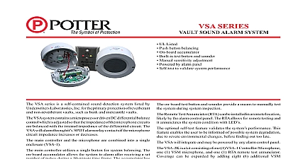
VAULT SOUND ALARM Listed 12 1 4 H x 8 3 8 W x 3 1 8 D 31,1cm H x 21,3cm W x 7,9 cm D 8 lbs 3,6 kg 18 Gauge Cold Rolled Steel Input 12VAC 20VA 60Hz Voltage 6VDC Current 20mA Current 25mA Ratings Alarm Relay and Tamper Switch 1.0 Amp at 28VDC 0.1 Amp at 130VDC Model VSA is a sound detection system listed by Underwriters Laboratories for the primary protection of reverberant and non reverberant vaults such as and mercantile vaults U L certi cation is required the VSA system must be installed in with U L 681 Including at least one manual initiating device in the and connection of the VSA to a U L listed control unit VSA ampli er unit is housed in a tampered steel cabinet with provisions for connections standby battery provides in excess of 80 hours operation in the event of a failure An external low voltage plug in transformer maintains the battery a fully charged state ampli er unit provides SPDT alarm relay contacts and provisions for 1 to 10 to be connected into the supervised microphone circuit VSA contains a DC differential balance control which is adjusted so that impedance of the external microphone circuit is balanced with the internal SEE FIGS 1 2 3 AND 4 of the differential circuit The VSA will alarm if the external impedance the microphone circuit increases or decreases microphones are available in surface mount Model PSM or ush mount PSM F Audio signals detected in the vault enclosure are fed to the er unit where the sensitivity control determines the sound level necessary alarm the unit Models PSM T surface mount and PSM FT ush mount are microphones a built in test sounding device One PSM T or PSM FT must be used in application alarm indicator light and test switch are provided for system testing by the Terminals are provided for remote subscriber and or central station Model APC Accumulating Pulse Counter is a plug in option which allows system to alarm after receiving a set number of pulses during a 10 minute time The pulse counter has an adjustable range of 1 to 9 pulses see page 4 If balance control will not adjust to this reading check wiring for open shorts must be balanced in order to set up in normal Mount VSA ampli er unit See Fig 7 Suggested Wire Routing Connect BLACK battery lead to NEGATIVE battery post Connect RED battery lead to POSITIVE battery post Plug in transformer to unswitched 110VAC outlet and apply 12VAC to 1 and 2 of VSA ampli er Mount microphones and wire according to installation drawing see Figs 1 3 and 4 Note A PSM T or PSM FT microphone with built in test sounding device be used in every installation See Fig 1 for connection of remote test unit Model PTU B and or central test unit if applicable Note Install jumper across terminals 12 and 13 if PTU B is not used of 10 microphones on each VSA ampli er Microphone circuit not exceed 1000 ft of 22 gauge 2 conductor shielded cable Maximum loop 1000 ohms Battery must be charged for 48 hrs before putting unit service ADJUSTMENT must be fully installed with all wires connected Adjust sensitivity to full CCW position Monitor balance adjustment jacks on circuit board with volt meter set on scale grounds ADJUSTMENT Adjust the SENSITIVITY control to approximately 1 3 scale Strike the vault surface with a plastic mallet and adjust the SENSITIVITY to provide desired protection EXTREME CARE SHOULD BE EXERCISED SO THAT THE SURFACES ARE NOT MARRED OR DAMAGED WHILE THE ATTACK TESTS test button on front of VSA ampli er applies test signal to sounding in PSM T or PSM FT causing the VSA to go into the alarm condition is indicated by a RED LED adjacent to the test button RED LED will not when sensitivity is set at 2 or below system will not test properly increase sensitivity control setting until reliable tests are obtained that reliable tests are obtained at remote test unit Model PTU B and or central station test unit if utilized subscriber must be instructed to test the system each time the alarm is set per on front of VSA ampli er unit SHOOTING VSA stuck in alarm check balance check battery and check wiring With removed from terminals 4,5,6 and 7 resistance across wires should 4 and 7 40 50 ohms for every microphone Jumper terminals 4 and 5 on VSA unit Note meter reading 4.2 to 5.2 volts Remove jumper from terminals 4 and 5 Adjust balance control to half of previous voltage reading 2.1 to 2.6 volts Electric Signal Company 2081 Craig Road St Louis MO 63146 4161 Phone 800 325 3936 Canada 888 882 1833 www pottersignal com IN USA 1 OF 4 Can not balance circuit check wiring make sure all wires and microphones connected to terminals 4,5,6 and 7 and 6 less than 10 ohms 8870002 REV M 1 VSA INSTALLATION SOUND ALARM system must be balanced after installation in order to set up in normal See balance instructions on page 1 2 SOUND ALARM SURFACE MOUNTED MICROPHONES IN USA 8870002 REV M 2 OF 4 3 SOUND ALARM FLUSH MOUNTED MICROPHONE 4 SOUND ALARM 5 APC ACCUMULATION PULSE COUNTER 6 Accumulation Pulse Counter Model APC is a plug in option designed for where extraneous sound levels penetrating the vault environment cause false alarms function of the APC option is to allow the system to detect and accumulate energy over a period of time and to cause an alarm condition when suf cient has been detected When used with the APC the purpose of the VSA is detect a single noise of high energy content For this reason the APC should adjusted such that it is more sensitive than VSA An amber LED on the APC when a noise pulse has been counted pulse counter control is adjustable from 1 to 9 This adjustment determines number of pulses required during a 10 minute time frame to alarm the unit A Pulse level exceeds counter threshold and accumulates B New 10 minute time frame starts Previous pulses erased C Pulse below counter threshold does NOT accumulate D Pulse accumulates E Pulse does NOT accumulate F and G Pulses accumulate H 10 minute time frame ends with 3 pulses accumulated pulse counter was set at 3 or below the unit would have alarmed If counter was set at 4 or above no alarm would have been received the 3 accumulated pulses erased A SINGLE PULSE EXCEEDS THE ALARM THRESHOLD THE UNIT ALARM IN USA 8870002 REV M 3 OF 4 SENSITIVITY ADJUSTMENT Set the VSA sensitivity control to 0 Set the APC pulse counter switch to the desired number 1 thru 9 the APC and produce the minimum noise level which the APC is to Adjust the APC sensitivity such that the yellow LED light blinks time this noise is produced disregard the red alarm light at this time Unplug and remove the APC Produce the minimum noise level at which the VSA should alarm and set VSA sensitivity control such that the red alarm LED comes on each this noise is produced This noise level should be much more intense that used to set the APC sensitivity Re install the APC pulse the noise used to adjust the APC sensitivity control until the VSA alarm illuminated red LED on the VSA unit The counter in the is now reset to 0 pulse this noise again When the number of pulses equals the switch on the APC the VSA will indicate alarm This veri es that both the and APC are operating properly at the desired noise level 7 SUGGESTED WIRE ROUTING SOUND ALARM INFORMATION Vault Sound Alarm System Surface Mount consists of Comp No 1 1 1 1 Ampli er with housing 12V 20VA 6V 4 AH Microphone Surface Mount ohm impedance Microphone with Sounding Device


