Potter VSG Waterflow Alarm Switch for Low Flow

File Preview
Click below to download for free
Click below to download for free
File Data
| Name | potter-vsg-waterflow-alarm-switch-for-low-flow-9054287316.pdf |
|---|---|
| Type | |
| Size | 713.51 KB |
| Downloads |
Text Preview
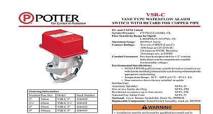
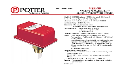
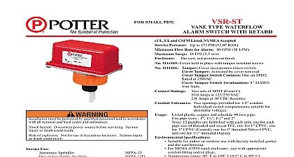
VSG FLOW RATE VANE TYPE WATERFLOW WITH ELECTRONIC RETARD ULC and CSFM Listed Pressure Up to 450 PSI 31 BAR Required for Alarm 3.0 GPM 11,4 LPM Surge 18 FPS 5,5 m s Requirements Ratings DPDT Form C Entrances 2 knockouts provided for 1 2 conduit Speci cations 10ma at 120V AC or 1.5ma at 24V AC DC 40ma at 120V AC or 35ma at 24V AC DC Suitable for indoor or outdoor use with factory installed Amps at 0 30VDC or 0 125VAC resistive and die cast housing NEMA 4 Rated Enclosure use with appropriate conduit tting Temperature Range 40 4,5 Non corrosive sleeve factory installed in saddle This device is not intended for applications in explosive OD and Wall Thickness use Water mist systems where low ow for alarm is 60,3mm OD 3,9mm to 4,5mm wall 1 2 73,0mm OD 4,8mm to 5,2mm wall 1 2 76,1mm OD 4,3mm to 4,7mm wall 88,9mm OD 5,0mm to 5,6mm wall 114,3mm OD 5,4mm to 6,4mm wall required Cover Tamper Switch Kit Stock No 0090018 Pat No 3921989 Canadian Pat No 1009680 Patents Pending Electric Rd 1990 Information Model VSG is a exible vane type of water ow switch for use in pipe water mist systems where a low ow for alarm is required It designed for installation in sections of 2 to 4 inch 50mm to 100mm steel or brass pipe with wall thickness in accordance with the speci cations see OD and Wall Thickness unit may also be used as a sectional water ow detector on large unit contains an output relay and an adjustable electronic retard relay is actuated when a ow of 3 gallons per minute 11,4 LPM or occurs downstream of the device The ow condition must exist a period of time necessary to overcome the selected retard period unit is enclosed in a general purpose die cast housing The cover held in place with two tamper resistant screws which require a special for removal A eld installable cover tamper switch is available as an which may be used to indicate unauthorized removal of the cover bulletin no 5400775 for installation instructions of this switch See Fig 1 devices may be mounted on a horizontal or vertical pipe On pipe they should be installed on the top side of the pipe they will be accessible The units should not be installed within 15cm of a tting which changes the direction of the water ow or 24 60cm of a valve or drain the system and drill a hole in the pipe using a circular saw in a speed drill The 2 50mm and 2 1 2 65mm devices require hole with a diameter of 1 1 4 1 8 1 16 32mm 2mm The 3 and 4 100mm devices require a hole with a diameter of 2 1 8 50mm 2mm the inside of the pipe of all growth or other material for a distance to the pipe diameter on either side of the hole the vane so that it may be inserted into the hole do not bend or crease Insert the vane so that the arrow on the saddle points in the direction the water ow Install the saddle strap and tighten nuts alternately to eventual 20 ft lbs 27 n m of torque See Fig 1 The vane must rub the inside of the pipe or bind in any way Electric Signal Company 2081 Craig Road St Louis MO 63146 4161 Phone 800 325 3936 Canada 888 882 1833 www pottersignal com IN USA 5400999 REV M PAGE 1 OF 2 FLOW RATE VANE TYPE WATERFLOW WITH ELECTRONIC RETARD 1 Adjustment retard time is selected by turning the switches to the off position For 45 seconds turn switches 1 and 3 to the off position time is as follows Switch Off 1 thru 8 On 1 1 2 1 2 3 1 2 3 4 1 2 3 4 5 1 2 3 4 5 6 7 8 Time in Sec used used 2 Typical Electrical Connections 3 Switch Terminal Connections Clamping Plate Terminal I N N I N 923 3 supervised circuits are used the following must be observed uninsulated section of a single conductor should not be looped the terminal and serve as two separate connections The must be severed thereby providing supervision of the in the event that the wire becomes dislodged from the terminal Warning to the possibility of unintended discharges caused by pressure surges trapped air or short retard times water ow switches that are monitoring pipe sprinkler systems should not be used as the sole initiating device to discharge AFFF deluge or chemical suppression systems The operation of the water ow switch and the associated alarms is to be tested upon completion of the installation and periodically in accordance with the applicable NFPA standards and or the authority having jurisdiction manufacturer recommends quarterly or frequently minimum ow of 3 GPM 11,4 LPM is required to activate this device IN USA 5400999 REV M PAGE 2 OF 2