Siemens DI-3, DI-3H, DI-3IS, DI-A3, and DI-A3H Smoke and Fire Detector, Installation Wiring Instructions

File Preview
Click below to download for free
Click below to download for free
File Data
| Name | siemens-di-3-di-3h-di-3is-di-a3-and-di-a3h-smoke-and-fire-detector-installation-wiring-instructions-1847925063.pdf |
|---|---|
| Type | |
| Size | 717.66 KB |
| Downloads |
Text Preview
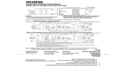
Installation Wiring Instructions and Fire Detector Models DI 3 DI 3H DI 3IS DI A3 and DI A3H initiating circuit of control See and Chart applicable for listed remote lamp or equivalent audible base or relay RR 3 40mA max at one per detector CAUTION Only critical function remote should be in each circuit since only one alarm circuit is guaranteed The Models DI 3 DI 3H DI 3IS DI A3 and are rated at 16 25.7 VDC volt peak to maximum ripple Supervisory current 110 steady state 350 peak surge upon of power and 135mA max in alarm The DI 3IS is FM listed only Do not use remote function with the DI 3IS 1 Models DI 3 DI 3H DI 3IS DI A3 AND DI A3H And Wiring Diagram 315 081882 Rev 2 instructions are written in accordance with the guidelines of NFPA 72 National Fire Alarm and CAN ULC S524 The Installation of Fire Alarm PLACEMENT no specific spacings have been allocated for the used for the 0 to 300 ft min clean air velocity use 30 foot center spacing 900 sq ft from NFPA 72 Chapter 5 and CAN ULC S524 if practical as a or starting point for a detector installation layout This however is based on ideal conditions smooth no air movement and no physical obstructions In applications therefore considerably less area is adequately by each smoke detector This is why it mandatory to closely follow the installation drawings In all except in special circumstances such as in room underfloors where the velocity may be 300 and 1200 ft min the detector should be located the ceiling a minimum of 6 inches from a side wall or on wall 6 inches from the ceiling questions arise regarding detector placement provided or approved by Siemens Industry Inc or its authorized distributors should be followed This is important The detector placements shown on drawings have been chosen after a careful evaluation 315 081943 19 all facets of the area being protected Such factors as air temperature humidity pressure and the nature of load have been carefully considered Especially noted have the room or area configuration and the type of ceiling or flat smooth or beamed Siemens Industry Inc s experience in the design of the system assures the detector placement and is reflected in these drawings engineering judgment by qualified personnel must AVOID NUISANCE ALARMS NOT locate the DI 3 DI 3H or DI 3IS detectors where smoke concentrations exist under normal conditions in areas of prolonged high relative humidity where will occur NOT locate the DI 3 DI 3H or DI 3IS detectors adjacent an oil burner kitchen or garage where exhaust fumes could an alarm Other causes of false alarms are dust high wind velocity heavy concentrations of heavy pipe or cigar smoke and certain aerosol sprays NOT locate the DI A3 or DI A3H detectors in an area of high relative humidity when condensation will occur adjacent to oil burners or in garages where exhaust fumes trigger an alarm Industry Inc Technologies Division CURRENTS NOTE HIGH STOCKPILING a detector can sense a fire the products of combustion smoke must travel from the fire to the detector Since their is especially influenced by air currents the movement air must be considered in the design of the system While products tend to rise drafts from hallways air fans etc may aid or hinder the travel of combustion to the detector When positioning a detector at a location consideration must be given to windows doors both open and closed and to influencing air A detector should never be installed in the air of a room air supply diffuser It may be advantageous position a detector closer to an air return distance that products of combustion or smoke travel a fire to the detector is not usually the shortest linear Combustion products or smoke usually rise to the then spread out With average ceiling height 8 to feet this will not be an abnormal factor Height should be into account however for high ceilings such as in warehouses auditoriums etc CEILING CONSTRUCTION FACTORS obstructions can change the natural movement of air combustion products Depending on the direction of travel joists and beams can slow the movement of air and smoke while pockets between them can a reduced level of smoke Take obstructions created girders joists beams air conditioning ducts or design into consideration when determining area Refer to the Initiating Devices chapter of NFPA 72 for Location and Spacing requirements for types of construction e g beam suspended level and peaked ceilings AND HUMIDITY temperature range for Models DI 3 DI 3H DI 3IS DI and DI A3H is 32oF 0oC to 100oF 37.8oC The four can each be used in environments where the humidity not exceed 93 non condensating changes of atmospheric pressure due to changes in have a negligible effect on detector sensitivity the lower air pressure at higher altitudes does have effect on the sensitivity of ionization type detectors to the following table general detector placement for high stockpiling requires spacing depending on the nature of the stock its height and the height of the building Newer recommend additional detector locations at lower levels Detector placement for this type hazard a judgment factor that can only be provided by qualified personnel ONLY in hazardous atmospheres The DI 3IS approved by Factory Mutual to protect areas identified as I Division 1 Groups A B C and D The intrinsically operation requires the use of a diode shunt barrier for 3 applications or a DC Isolator for MXL CZM 1 1B6 For System 3 applications refer to the Model Installation Instructions P N 315 091465 For CZM 1 1B6 applications refer to the CZM 1 Installation P N 315 090725 or the CZM 1B6 Installation P N 315 095355 as applicable WIRING Industry Inc detectors should be interconnected shown in Figure 1 and wired to the control panel by the Wiring Connection drawing installed on the face of each control panel cover Duplicate wiring is also contained in the Installation Operation Maintenance manual provided with every control panel should be made of any limitations on the number of permitted on each circuit Quantities may vary on the specific type of response designed into the fan shutdown door closing external relay tie in system discharge etc MOUNTING detector is provided with a separate base which attaches a standard 4 inch square 4 inch octagonal or single outlet electrical box The depth of the box is determined the National Electrical Code for the number and size of conductors used MOUNT Route all wires outward outlet box When the alarm LED critical the LED mark in base in the intended See Figure 2 Mount base to outlet box route wires through hole in the center of Make directly to base terminals to Figure 1 for 2 After all bases are installed including the end of line check loop continuity Refer to system operation for procedure To make the continuity check a is furnished in every base between terminals 1a 1b to complete the loop See Figure 2 An open cir condition exists until the jumper or detector is installed the base loop continuity is acceptable remove jumper at each location and proceed with detector head To insure proper installation of the detector head into base be sure wires are properly dressed at installation Position all wires flat against the base Take up all slack in the outlet box Route wires away from connector terminals