Siemens EB-32, EB-33 and EB-35 System 3 Control Panel Enclosures, Installation and Power Limited Wiring Instructions

File Preview
Click below to download for free
Click below to download for free
File Data
| Name | siemens-eb-32-eb-33-and-eb-35-system-3-control-panel-enclosures-installation-and-power-limited-wiring-instructions-2648573091.pdf |
|---|---|
| Type | |
| Size | 690.50 KB |
| Downloads |
Text Preview
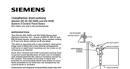
Installation and Power Limited Wiring Instructions EB 32 EB 33 and EB 35 3 Control Panel Enclosures indoor use only in dry environments EB 32 EB 33 and EB 35 Enclosures See Figure from Siemens Industry Inc are designed to accom System 3 control panels input and output and all power supplies utilized in the system can be either surface or semi flush mounted enclosure consists of a back box and door cover fabricated of heavy gauge sheet steel The box which is finished in a black enamel is for mounting the Z brackets and U supports on which are mounted the controls and power supplies fasten the control panel enclosure to a shock vibration free surface in a clean dry area It be mounted with the top of the enclosure 6 feet above the floor The location ensure that the control panel is easily visible readily accessible for maintenance Leave room to open the enclosure door should be in accordance with national and local for fire alarm circuits For AC supply power use 14 or larger AWG 600V insulation wire Remove knockouts in the backbox where field is required Refer to Table 1 Table 2 and 1 Hold the empty enclosure against the wall at the height Mark drill points on the wall in the center of the slots on the upper rear of the box Refer to 1 Drill the two holes and screw in the top bolts a small gap between the wall and each bolt Industry Inc Technologies Division Park NJ 315 093680 9 Mount the enclosure on the two bolts and then the bottom bolts Tighten all bolts securely against the back wall of enclosure Pick up the module frame assembly by the straps at the end of the wiring channels Do not hands behind the modules as the circuitry be damaged the module frame assembly in the enclo securing it to the studs with the 5 16 inch provided Do not overtighten nuts do not use type wrench as the studs can be if excessive force is applied compliance with UL 864 all power limited fire signaling conductors must be separated a of inch from all of the following items within a control panel electric light power Class 1 or non power limited signaling conductors meet these requirements the following guidelines be observed when installing modules and to a System 3 control panel installing power limited field wiring the installer comply with NEC article 760 54 which states fire alarm power limited circuits are installed Types FPL FPLR FPLP or permitted cable provided these power limited conductors extending beyond the jacket are by a minimum of 0.25 in 6.35 mm or a nonconductive sleeve or nonconductive from all other conductors Canada Limited Technologies Division Kenview Boulevard Ontario L6T 5E4 Canada ENTERING THE ENCLOSURE Limited Wiring to the System 3 module terminations shown in 2 is considered power limited and must enter the knockouts in the top left side of the See Figure 2 LEAVING THE ENCLOSURE Limited Wiring power limited wiring is desired for audible use the model PLM 35 Refer to the PLM 35 Instructions P N 315 093495 for informa on installation of the module and wiring to the circuits power limited wiring is not used within a 3 enclosure the following guidelines not apply In that case be sure to follow wiring practices ENTERING THE ENCLOSURE Limited Wiring to the System 3 module terminations shown in 1 is considered non power limited and must through the knockouts in the top right side of the See Figure 2 Wiring between the knock specified and the module termination must be in shortest route and must not overlap any other IN THE ENCLOSURE Limited Wiring from the batteries to the BC 37 is considered limited To maintain the required separa the wiring must be routed in the right side of the wiring within the enclosure must be routed as in Figure 2 To maintain the required inch spacing tie wrap the wiring to the mounting screws Enclosure EB 32 EB 33 EB 35 in 52.07 cm in 56.83 cm in 62.23 cm in 78.74 cm in 83.50 cm in 88.95 cm in 39.37 cm in 132.08 cm 7 8 in 136.84 cm in 142.24 cm in 66.04 cm 3 Enclosure Mounting Dimensions 1 LIMITED LIMITED LIMITED POWER LIMITED NON POWER LIMITED 2 3 Power Limited Wiring Industry Inc Technologies Division Park NJ 315 093680 9 Canada Limited Technologies Division Kenview Boulevard Ontario L6T 5E4 Canada