Siemens SM-30 Switch Module, Installation Instructions
File Preview
Click below to download for free
Click below to download for free
File Data
| Name | siemens-sm-30-switch-module-installation-instructions-6372985041.pdf |
|---|---|
| Type | |
| Size | 617.86 KB |
| Downloads |
Text Preview
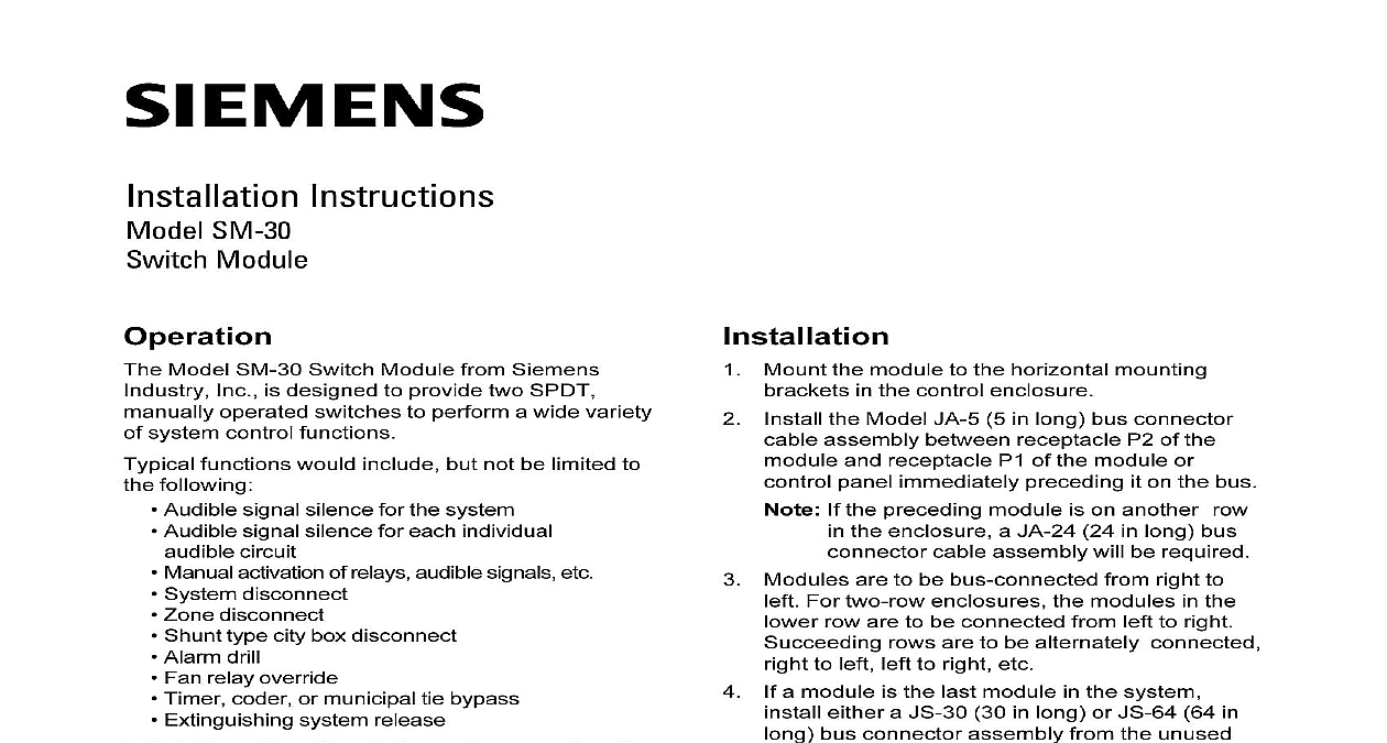
Operation Instructions SM 30 Module Model SM 30 Switch Module from Siemens Inc is designed to provide two SPDT operated switches to perform a wide variety system control functions functions would include but not be limited to following Audible signal silence for the system Audible signal silence for each individual circuit Manual activation of relays audible signals etc System disconnect Zone disconnect Shunt type city box disconnect Alarm drill Fan relay override Timer coder or municipal tie bypass Extinguishing system release their Normal position during system operation the provide a single pole double throw SPDT through screw terminals The yellow LED mounted on the face of the module one for switch are not illuminated When the switches manually thrown to Operated position the SPST condition is reversed and their yellow LED are illuminated The contact rating of the is 0.5 amp 30 VDC or 120 VAC is also provided within the module to indicate trouble when a switch is in an abnormal if so desired double pole double throw DPDT switch version the SM 30 module is available with two switches is available on special order In this configuration LEDs and system trouble interconnects are not Mount the module to the horizontal mounting in the control enclosure the Model JA 5 5 in long bus connector assembly between receptacle P2 of the and receptacle P1 of the module or panel immediately preceding it on the bus If the preceding module is on another row the enclosure a JA 24 24 in long bus cable assembly will be required Modules are to be bus connected from right to For two row enclosures the modules in the row are to be connected from left to right rows are to be alternately connected to left left to right etc a module is the last module in the system either a JS 30 30 in long or JS 64 64 in bus connector assembly from the unused of the last module to terminal 41 of the control panel This completes the module circuit Wire the terminals as shown in the Typical Wiring on the back of this sheet a trouble condition is indicated check that are in Normal position s Industry Inc Technologies Division Park NJ 315 021311 9 Building Technologies Ltd Safety Security Products Kenview Boulevard Ontario 5E4 Canada Wiring WIRE SIZE 20 AWG WIRE SIZE 14 AWG OPERATING POWER 24V 10mA 315 021311 9