System Sensor 2112 24TSRB

File Preview
Click below to download for free
Click below to download for free
File Data
| Name | system-sensor-2112-24tsrb-3208594617.pdf |
|---|---|
| Type | |
| Size | 681.40 KB |
| Downloads |
Text Preview
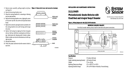
A Division of Pittway 3825 Ohio Avenue St Charles Illinois 60174 FAX 630 377 6495 AND MAINTENANCE INSTRUCTIONS Photoelectronic Detector 5.5 inches 140 mm including mounting bracket 1.7 inches 43 mm 5.3 oz 150 g Temperature Range 32 to 100 0 to 39 Humidity Range 10 to 93 relative rumidity noncondensing Alarm Reset by momentary power interruption Sensor 135 fixed temperature electronic thermistor Ratings Voltage nominal Minimum Maximum Ripple Voltage 30 of nom voltage peak to peak Current 15 mA maximum Current at 12V 38 mA maximum at 24V Voltage 0.8 VDC minimum Time 0.3 seconds maximum Time 30 seconds maximum after 30 second reset and Alarm Initiation Contact Ratings or inductive load 60 power factor A 0.5A 30 VAC DC or 24 VDC VDC VDC mA maximum Installing thoroughly read System Sensor manual I56 407 for Proper Use of System Smoke Detectors which detailed information on detector spacing place zoning wiring and special applications Copies of manual are available at no charge from System Sensor This manual should be left with the owner user this equipment This detector must be tested and maintained NFPA 72 requirements The detector should be at least once a year Description Model 2112 24TSRB is a 4 wire photoelectronic smoke that uses a state of the art optical sensing cham This detector is designed to provide open area pro It features a restorable built in fixed temperature thermal sensor of this detector is simplified by the use of the bracket and plug in screw terminal block that be prewired to the system allowing the detector to easily installed or removed for cleaning The detector can be tested in place using the MOD400R Test available separately from System Sensor 2112 24TSRB features a supervisory relay that super the power and the sensitivity of the detector When power to the detector is lost the supervisory relay instantaneously Where as when the detector devi from its sensitivity range indicating the need for main the supervisory relay opens after a maintenance has continuously existed for 30 to 35 minutes LED on the detector provides a local visual indication the detector status If power is applied to the detector it is functioning normally in standby the status LED every ten seconds The LED latches on in alarm and flashing when the detector deviates from its sensitiv range 1 I56 930 02 1 Surface mounting of 2112 24TSRB smoke on 31 2 inch and 4 inch octagonal box 2112 24TSRB detector is supplied with a mounting that permits the detector to be mounted To a single gang box or Directly to a 31 2 inch or 4 inch octagonal box or To a 4 inch square electrical box by using a plaster ring Feature detector includes a tamper resistant feature that pre its removal from the bracket without the use of a To make the detector tamper resistant remove the tab by breaking it at the scribed line on the tamper tab on the detector mounting bracket see Figure then install the detector To remove the detector from bracket once it has been made tamper resistant use small screwdriver to depress the tamper resistant tab in the slot on the mounting bracket and turn the counterclockwise Installation Guidelines wiring must be installed in compliance with the Na Electrical Code applicable local codes and any spe requirements of the local authority having jurisdiction wire gauges should be used The conductors used connect smoke detectors to control panels and accessory should be color coded to reduce the likelihood of errors Improper connections can prevent a system responding properly in the event of a fire 2 Smoke detector mounting bracket screw terminal block accepts 14 22 gauge wire For system performance all wiring should be installed in grounded conduit Do not mix fire system wiring the same conduit as any other electrical wiring Twisted may be used to provide additional protection against interference detectors and alarm system control panels have for allowable loop resistance Consult the panel specifications for the total loop resistance for the control panel being used before wiring the loops connections are made by stripping about 1 4 inch of from the end of the feed wire inserting the wire the appropriate terminal and tightening the screw to the wire in place Trouble relay must be wired last in the circuit power from the control unit or initiating device before installing detectors Wire the plug in screw terminal block per Figure 3 and the terminal block into the detector Align the arrows on the detector with the arrows on the Turn the detector clockwise in the mounting bracket un bracket it clicks into place After all detectors have been installed apply power to control unit or initiating device circuits Test the detector as described in TESTING Reset the detector at the system control panel Notify the proper authorities the system is in operation SLOT TAB TO DETECTOR RESISTANT TAB CUT OFF SMALL TAB TO ACTIVATE TAMPER RESIST FEATURE 2 I56 930 02 3 Wiring diagram for the 2112 24TSRB detector LISTED RESISTOR BY CLASS A WIRING covers are an effective way to limit the entry of dust smoke detector sensing chambers However they may completely prevent airborne dust particles from en the detector Therefore System Sensor recommends removal of detectors before beginning construction or dust producing activity Be sure to remove dust covers any sensors that were left in place during construction part of returning the system to service Before testing notify the proper authorities that the detector system is undergoing maintenance will be temporarily out of service Disable the or system undergoing maintenance to prevent alarms must be tested after installation and following maintenance Test the 2112 24TSRB as follows Test Switch 1 A recessed test switch is located on the detector hous See Figure 4 2 Press and hold the recessed test switch with a 0.1 maximum diameter tool such as an allen wrench small screwdriver 3 The detector LED should light within 5 seconds Test Module System Sensor Model No MOD400R The MOD400R test module can be used with a DMM analog voltmeter to check the detector sensitivity as in the test module manual Smoke Entry Test Hold a smoldering punk stick or cotton wick at the side the detector and gently blow smoke through the de until the unit alarms Direct Heat Method Hair dryer of 1000 1500 watts Direct the heat toward either of the side thermistors the heat source about 12 inches from the detector order to avoid damage to the plastic The detector will on