System Sensor DH500 DH500ACDC

File Preview
Click below to download for free
Click below to download for free
File Data
| Name | system-sensor-dh500-dh500acdc-7458691203.pdf |
|---|---|
| Type | |
| Size | 1.31 MB |
| Downloads |
Text Preview
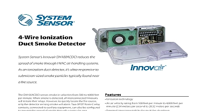
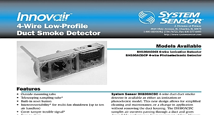
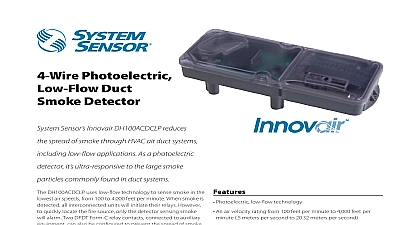
500 Series Smoke Detector Division of Pittway Ohio Avenue St Charles IL 60174 736 7672 Fax 630 377 6495 Available Duct Smoke Sensor Housing Duct Smoke Sensor Housing with Fan Control DH500 DH500ACDC from the control panel communication line outputs for remote LED output remote test 24 Continuous sensitivity monitoring from the panel Intelligent ion or photo heads with twist in twist out Air velocity rating from 500 to 4000 fpm Remote test station and remote annunciator accessories Clear polycarbonate cover for convenient visual of sampling tube filters UL 268A listed 3 year warranty VAC DC or 120 220 VAC operation outputs for remote LED remote test and Form C auxiliary contacts supply is required only when using the relay or connecting any accessories DH500 Range Current 28 VDC peak at 24 VDC Surge at Rated Voltage mA sec Current nominal 6 mA at 24 VDC inches 36.7 cm inches 12.7 cm inches 10.2 cm lbs 1.8 kg Range to 120 F 0 to 49 C Range Air Velocity to 93 relative humidity 4000 ft min 1219.2 m min System Sensor 4 97 document is not intended to be used for installation purposes Description Sensor premium duct detectors Models DH500 DH500ACDC feature the superior capabilities of an sensor in a unit that is easy to install and The DH500 Series Duct Housing samples air passing through a duct and gives dependable for shutdown of fans blowers and air systems preventing the spread of toxic and fire gases through the protected area Model DH500 and DH500ACDC duct housings can either the 1551B Intelligent Ionization or the 2551B Intelligent Photoelectronic Sensor twist in twist out heads allow for quick and easy or application changes without removing the duct sensors communicate and are continuously through the communication line Detector changes caused by dirt smoke temperature or are reported to the panel allowing compensation to maintain the sensor set sensitivity An indication at the panel specifies the sensor allowing for selected maintenance to be as needed alarm annunciation can be accomplished by the RA400Z Remote Annunciator or the RTS451 or Remote Test Station The RTS451 and allow testing of the detector from a remote The detector must be reset from the control Model DH500 incorporates zener diodes to conserve for communications to other devices and limit to supplementary accessories at times of high demands Duct smoke detectors have specific limitations DETECTORS ARE a substitute for an open area smoke detector a substitute for early warning detection and a replacement for a building regular fire system to NFPA 72 and 90A for additional duct detector information Specifications air duct smoke detector shall be a System Sensor DH500ACDC or DH500 Intelligent Series Smoke Detector to be used with compatible control units detector housing shall be UL listed per UL 268A for use in air handling systems The detector operate in air velocities from 500 to 4000 feet per The detector housing shall be equipped with an mounting base capable of accommodating either photoelectronic or intelligent ionization detector It shall be capable of local testing via magnetic or remote testing from the RTS451 or RTS451KEY Test Station The duct detector housing shall an airtight smoke chamber in compliance with 268A Standard for Smoke Detectors for Duct The housing shall be capable of mounting to rectangular or round ducts without adapter An integral filter system shall be included to dust and residue effects on detector and housing reducing maintenance and servicing Sampling shall be easily installed after the housing is mounted the duct by passing through the duct housing Terminal shall be of the strip and clamp method for 14 AWG wiring Wiring shall be connected a terminal strip and be so noted or ALARM OPTION PER UNIT CURRENT DRAW break tab back of when with POWER or OPTION PER UNIT CURRENT DRAW COIL OPTION PER UNIT CURRENT DRAW TEST STATION Listed Panel Loop Loop Wiring Diagram for DH500 Duct Smoke Detector Using a UL Listed Control Panel 2 VDC 20 DC maximum VAC 120 132 VAC 204 rms maximum VAC 20.6 rms maximum Power Supply Electrical Ratings mA rms maximum currents shown for the DH500ACDC are maximum values with no accessories accessory currents are additional to DH500ACDC There are no additional currents for accessories in standby devices draw current when the magnet is held in place to initiate an alarm Relay Contacts amps maximum at 30 VDC 10 amps maximum at 277 VAC Hp at 240 VAC 360 VA at 240 VAC Specifications requirements for intelligent system control The panel must not continuously poll the same unit for than 3 seconds or the auxiliary relay and alarm output could switch states After 3 of continual polling of a device the panel must a minimum of 100mS before polling or to that same device Communications must not cease for more than 3 VAC VDC JUMPER WIRE J5 REQUIRED TO BE FOR 2 WIRE CUT J5 FOR SUPERVISION EXTERNAL IS USED PANEL VAC VAC RUN AUXILIARY CONTROL IN SEPARATE CONDUIT TO REST SYSTEM FOR POWER SUPPLY POLARITY IS NOT Wiring for DH500ACDC auxiliary output maximum load is 80 mA output maximum load is 20 mA without an additional clock pulse after Pulse 5 to turn off the LED on the sensor To allow the auxiliary relay and auxiliary alarm output return to a standby condition after being in alarm panel must wait a minimum of 100mS after turning the sensor LED before re communicating to the device SAMPLING TUBE SEPARATELY HOLES DETECTOR BOARD DETECTOR TUBE BASE SCREWS ADAPTER HEAD SEPARATELY MAGNET TUBE View of DH500ACDC Smoke Detector Components 10 15 SIGNAL POWER POWER DETECTOR USED TEST OPTIONAL TEST THE RTS451 RESET CANNOT BE USED ON THE 500 SERIES SIGNAL POWER SIGNAL POWER DETECTOR OPTIONAL ALERT DETECTOR NOT BREAK TAB RA400Z OPTIONAL LED 3 Wiring