Wheelock E60H high fidelity speaker install sheet P85325

File Preview
Click below to download for free
Click below to download for free
File Data
| Name | wheelock-e60h-high-fidelity-speaker-install-sheet-p85325-0752369841.pdf |
|---|---|
| Type | |
| Size | 942.07 KB |
| Downloads |
Text Preview
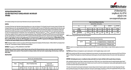
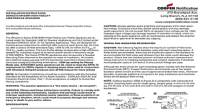
INSTALLATION INSTRUCTIONS E60H HI FIDELITY ROUND AND SPEAKER STROBES this product according to this instruction manual Please keep this instruction manual for future reference Wheelock Series E60H High Fidelity Round Speakers and Speaker Strobes are UL Listed under Standard 1971 for Signaling Devices for the Hearing Impaired UL 1480 for Speaker Appliances and ULC Listed under Standard CAN ULC S541 07 AND CAN ULC S526 07 Speaker Strobes with amber blue green and red lens UL Listed under Standard 1638 Visual Signaling Appliance for Private Mode Emergency and General Utility Signaling They are designed for multiple power require with high dBA output at each power tap All models offer a choice of field selectable taps 1 8W to 2W for either 25.0 VRMS or 70.0 VRMS audio systems The design a high efficiency speaker for maximum output at minimum power across a frequency range of 300 8000Hz The Series E60H appliances also incorporate a mounting plate attached to the speaker for ease of installation The Speaker Strobes can provide a non synchronized strobe appliance when connected directly to Fire Alarm Control Panel FACP or provide a synchronized strobe appliance when used in conjunction with a Dual Sync Module DSM or Wheelock power supplies The use a xenon flashtube with solid state circuitry enclosed in a polycarbonate lens to provide maximum visibility and reliability for effective visible signaling The E60H and E60H 24MCCH Speaker Strobes are for ceiling mounting only All models are Listed for indoor use only with the back boxes specified in these instructions see and Mounting Information 1 8W tap setting for Private Mode only E60H series speakers are UL rated to meet the NFPA 72 requirement for 520Hz signals in areas when used in conjunction with Wheelock Safepath products see SP40S manual for more details All Canadian Installations should be in accordance with the Canadian Standard for the Installation of Fire Alarm Systems CAN ULC S524 and Canadian Electrical Part 1 Final acceptance is subject to Authorities Having Jurisdiction Please read these instructions carefully Failure to comply with any of the following instructions cautions and warnings could result in improper ap installation and or operation of these products in an emergency situation which could result in property damage and serious injury or death to you and others 1A UL ULC Listed Models and Ratings at 10 Feet Rated Watts 1B UL ULC Listed Models and Ratings dBA CAN ULC S541 07 MCC Candela Strobes produce 1 flash per second over the Voltage range All models are Listed for indoor use with a temperature range of 32 to 120 0 to 49 and maximum humidity of 93 RH The effect of shipping and storage shall not adversely affect the performance of the appliance when it is stored in the original cartons and is not subjected to misuse or abuse The maximum supervision voltage is 33 volts DC Frequency range of speakers is 300 8000Hz Strobes with clear and amber lens meet the required light distribution defined in UL1971 Candela ratings are for clear lens Derate approximately 25 for amber lens 55 for green 70 for blue and 80 for red Model numbers will have a letter after the H designate lens color A G B or R Always operate audio amplifiers and speakers within their specified ratings Excessive input may distort sound quality and may damage audio equipment Do not 100 of speaker input voltage per UL 1480 Improper input voltage can damage speaker If distortion is heard check for clipping of the audio appliance with an oscil and reduce the amplifier input level or gain level to eliminate any clipping Candela setting will determine the current draw of the product These strobes are Listed as They are intended to be used with FACPs whose notification circuits are Listed as These appliances shall be used on UL Listed Application notification circuits unless the appliances are identified to be compatible in the installation instructions of the FACP is identi to be compatible in this instruction manual Voltage 2 Current Ratings with Strobe Only Maximum RMS Current AMPS 3 ULC Directional Characteristics 34 degrees horizontal 17 degrees 40 degrees horizontal 32 degrees These strobes were tested to the regulated voltage limits of 16.0 33.0 Volts for 24v models using filtered dc or unfiltered full wave rectified voltage Do apply voltage outside of this range Check the minimum and maximum output of the power supply and standby battery and subtract the voltage drop from the circuit wiring resistance to the applied voltage to the strobes The maximum wire impedance between strobes shall not exceed 35 ohms Strobes are not designed to be used on coded systems in which the applied voltage is cycled on and off Make sure the total RMS current required by all appliances that are connected to the system primary and secondary power sources notification ap circuits Wheelock dsm sync modules or Wheelock power supplies do not exceed the power sources rated capacity or the current ratings of any fuses on circuits to which these appliances are wired Overloading power sources or exceeding fuse ratings could result in loss of power and failure to alert occupants an emergency which could result in property damage and serious injury or death to you and or others AND MOUNTING INFORMATIONCAUTION The following figures show the maximum number of field wires conductors that can enter the backbox used with mounting option If these limits are exceeded there may be insufficient space in the backbox to accommodate the field wires and stresses from the wires could dam the product Check that the installed product will have sufficient clearance and wiring room prior to installing backboxes and conduit especially if sheathed multicon cable or 3 4 inch 1.9 cm conduit fittings are used the limits shown for each mounting option comply with the National Electrical Code NEC Cooper Notification recommends use of the largest backbox option and the use of approved stranded field wires whenever possible to provide additional wiring room for easy installation and minimum stress on the product from Branchport Ave Long Branch N J 07740 800 631 2148 www coopernotification com1PN P85325CCopyright 2015 Cooper Wheelock Inc dba Cooper Notificationfirealarmresources com candela select switch may result in operation at the wrong candela which could result in property damage and serious injury or death to you and or others PROCEDURES All models can be flush mounted to a 4 inch square by 2 1 8 inch 10.16 cm by 5.4 cm deep backbox with a 4 inch 1 1 2 inch 10.16 cm by 3.8 cm sq extension Figure A Mounting hardware is supplied Conduit entrances to the backbox should be selected to provide sufficient wiring clearance for the installed product Do not pass additional wires used for other than signaling appliance through the backbox Such additional wires could result in insufficient wiring space for the signaling appliance When terminating field wires do not use more lead length than required Excess lead length could result in insufficient wiring space for the signaling appliance Use care and proper techniques to position the field wires in the backbox so that they use minimum space and produce minimum stress on the product This is espe important for stiff heavy gauge wires and wires with thick insulation or sheathing The speaker strobe has an integrated speaker mounting plate which must be oriented correctly before mounting the unit to the back box See Figure B for correct To move selector switch insert screwdriver into slot shown on the bottom side of the strobe The setting is indicated by a pointer and can be seen on the bottom side orientation the lens See Figure 5 move Figure 1 Figure 2 Wiring method shall be in accordance with CSA C22.1 Canadian Electrical Code Part 1 Safety Standard for Electrical Installations Section 32 First mount the mounting plate to the backbox and fasten it with two screws Next snap the grille to the mounting