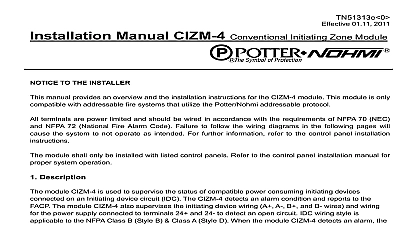
Potter CIZM-4 Conventional Initiating Zone Module

File Preview
Click below to download for free
Click below to download for free
File Data
| Name | potter-cizm-4-conventional-initiating-zone-module-4165093278.pdf |
|---|---|
| Type | |
| Size | 1.68 MB |
| Downloads |
Text Preview
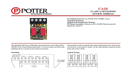
Features Compatible with conventional 2 wire smoke detectors IDC can be wired Class A or Class B Monitors presence of 24VDC Aux Power SLC Class A Style 6,7 Class B Style4 Mounts in a standard 4 or double gang box Wiring terminals accessible when mounted in box All wiring terminals accept 22 to 14 AWG Product includes a 5 year warranty Number 1430823 CIZM 4 is compatible with Potter PFC 6000 series and PFC addressable re alarm control panels The CIZM 4 is used to a zone of conventional 2 wire smoke detectors on an Device Circuit IDC CIZM 4 module uses one 1 address on an SLC Loop and a zone of 2 wire conventional smoke detectors The module and supervises a 24VDC auxiliary power connection The may be wired Class B Style B or Class A Style D which is by an on board jumper The CIZM 4 employs one red LED indicate the modules status In normal condition the LED ashes the device is being polled by the control panel When a device activated the LED will light continuously and in case of an open the LED will turn off Initiating Zone Module Speci cations Voltage SLC Standby Current Power Required Voltage Range of IDC Detector Standby Current IDC at 24 VDC Module Alarm Current of at 24 VDC Wiring Resistance of IDC Wiring Cpacitance of IDC Resistor Tempurature Range Humidity Range no of Module Per Loop 22.6V Options Weight to 120 0 to 49 to 93 non condensing units 106mm L 4.17 1.14 29mm 4 Square or Gang Box lbs Electric Signal Company LLC St Louis MO Tech Support 866 956 0988 Customer Service 866 572 3005 www pottersignal com REV D 7 14 PAGE 1 OF 3 the Address SLC device must be assigned an address prior to installation The address is set using either the hand held device programmer or the addressing feature thePFC 6800 PFC 8500 series control panels connecting a device to the SLC loop take the following precautions to prevent potential damage to the panel or device verify the following Power to the device is removed Field wiring is correctly installed Field wiring has no open or short circuits Diagrams Class B Wiring Diagram Class A Wiring Diagram FACP or Previous Module Loop Next Module FACP or Previous Module Next Module FACP or Previous Module Loop Next Module FACP or Previous Module Next Module The resistance of external wiring shall be less that 100 capacitance of external wiring shall be less than 1 micro farads Detector Initiating Zone Module No CIZM 4 1 2W EOLR The resistance of external wiring shall be less than 100 capacitance of external wiring shall be less than 1 micro farads Style D Detector Initiating Zone Module No CIZM 4 PAGE 2 OF 3 REV D 7 14Potter Electric Signal Company LLC St Louis MO Tech Support 866 956 0988 Customer Service 866 572 3005 www pottersignal comCIZM 4Conventional Initiating Zone Modulefirealarmresources com Using Compatible Electrical Box 2 Wire Smoke Detectors No Approval No No Approval No No Sensor remote annunciator remote annunciator Hochiki Hochiki PAGE 3 OF 3 REV D 7 14Potter Electric Signal Company LLC St Louis MO Tech Support 866 956 0988 Customer Service 866 572 3005 www pottersignal comCIZM 4Conventional Initiating Zone Modulefirealarmresources com