Siemens SLT-1 Leased Line Municipal Tie Module, Installation Instructions

File Preview
Click below to download for free
Click below to download for free
File Data
| Name | siemens-slt-1-leased-line-municipal-tie-module-installation-instructions-9406318527.pdf |
|---|---|
| Type | |
| Size | 780.90 KB |
| Downloads |
Text Preview
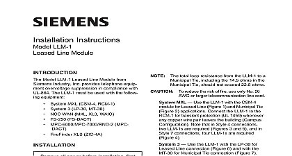
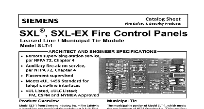
Installation Instructions SLT 1 Line Municipal Tie Module Model SLT 1 module from Siemens Industry is used with the SXL EX System to provide for Leased Line and or Municipal Tie or both connections can be used Terminal 1 See Figure 1 provides the connection to on the Main Board the green LED labeled DS1 on the module is it indicates that the module is active with SLT 1 Rev 1.1 and higher and Rev 2.0 or higher the SLT 1 will ener the municipal tie connection for one minute the last alarm received at the panel Mod with firmware below this level will energize municipal tie connection until the panel is SLT 1 Rev 1.1 and higher and SXL EX Rev or higher the municipal tie box can be reset the panel is reset The SLT 1 continues to the Leased Line connection until the is reset for all firmware versions SLT 1 causes a trouble on the display panel any of the following three conditions There is an open on the data line No SLT 1 module is connected to the System there is an address for the module in System configuration An SLT 1 module is connected to the system there is no address for it in the System LED Line Tie 1 Module all system power before first battery and then AC power up connect the AC and then the battery in SXL EX System to Figure 2 the SLT 1 in the upper right hand portion of EN SX enclosure according to the following the four 6 32 x 1 2 standoffs over the studs in the upper right hand corner of SXL EX enclosure as shown in Figure 2 Place the upper four holes of the SLT 1 board the four standoffs in the upper right hand of the EN SX enclosure Using the 6 32 screws provided fasten the SLT 1 to the standoffs Industry Inc Technologies Division Park NJ 315 093285 10 Building Technologies Ltd Safety Security Products Kenview Boulevard Ontario 5E4 Canada the SLT 1 in an SXL EX System 2 an Existing SXL System to Figure 3 place the SLT 1 on the Main Board of an system first remove the existing Display and its cover according to the following Remove the Display Cover from the Display as shown in Figure 3 Discard its top standoffs Unplug the ribbon cable from the Display at jumper JP4 on the Main Board Remove the Display Board from the SXL Board by unscrewing the four 6 32 and setting them to one side supporting the two upper corners of Display Board Use the four 6 32 x 1 7 8 standoffs the 6 32 and the two 15 16 standoffs provided follows Fasten one of the longer standoffs provided the back of the upper left hand corner of SLT 1 with the screw provided Remove the screw from the upper right corner of the Main board Screw another long standoff to the upper corner of the Main board Screw the last two long standoffs provided the Main board as shown in Figure 3 Place the SLT 1 module on the standoffs that installed in Step 5 above Fasten the two short standoffs remaining to bottom two corners of the SRC 8 board are supports for the Display Board Once the SLT 1 is in place re install the Board by reversing Steps 1 3 above the SLT 1 in an Existing SXL System 3 SXL Program Level 9 to program the SLT 1 Refer to the SLX EX Manual P N 315 To enter the System Press the RESET and DRILL keys at the time under PROGRAM MODE in the Press the SILENCE key to confirm the for the system An A should display in the 7 segment an F appears repeat the process until A appears To enter the Program Mode Press the ACK key once Note that a P displays in the 7 segment Be sure the PROGRAM TEST LED is lit To select the desired Program Mode To select Program Level 9 press RESET button 9 times Press SILENCE Remove and discard the two standoffs that Enter your password Refer to Enter To program the SLT 1 Program Level 9 has one sublevel The is displayed on the 7 segment following the hyphen Note that the top yellow LED on the is lit Press the RESET key three times to on the fourth yellow LED the fourth red LED is on the SLT 1 activated the fourth red LED is not on the is not activated Press the DRILL key to toggle between ON and OFF de activated as To exit the system Press the ACK key until an L ap pears on display Press SILENCE to exit the program Electrical Characteristics to Figure 4 TB1 on the SLT 1 to TB 3 on the SXL EX Board being sure to observe the terminal 24V V DATA EARTH Connections for 72 Municipal Tie to Figure 4 All wiring must be in accordance with Article of NEC or local building codes Minimum wire size 18 AWG Electrical Ratings Coil 14.5 ohms Current 240mA DC max Current 1mA DC 18.3 24.1 VDC open circuit voltage external resistance should not exceed ohms Minimum emergency power hour standby minute alarm Connections for 72 Leased Line to Figure 4 All wiring must be in accordance with Article of NEC or local building codes Leased line is power limited to NFPA 70 Article 760 Leased line circuit rating 24 VDC open circuit must be a compatible polarity reversal remote station receiver unit 18.3 24.1 VDC current 3mA to 9mA alarm circuit resistance 2K to 5K ohms Minimum emergency power hour standby minute alarm and Negative Fault Detected at For Terminals on TB1 Line SLX EX Board TB 3 Limited 4 Tie 4 the SLT 1 and Negative Ground Fault at 80K for terminals on TB2 and TB3 Line Limited Tie shown in state Municipal Tie is not install 1K ohm watt resistor 140 112315 CALCULATIONS backup is required for the SLT 1 To the size battery you need refer to the calculation table in the SXL EX Manual 315 095997 AND TESTING periodic maintenance is required however Building Technologies Inc does periodic testing Before testing you MUST notify the in charge of the Fire Alarm since the test may disrupt normal operations In addition you notify the local Fire Department if department is connected to the tie and or the leased line Operation with SLT 1 Rev 1.1 or higher and Rev 2.0 or higher the municipal tie voltage returns to normal one minute the last alarm If the module is connected to municipal box the panel will display Fault 5 indicating that the box needs to be reset SLT 1 Rev 1.1 or higher and SXL EX Rev or higher the municipal tie box can be reset the panel is reset the leased line and the municipal tie for alarm by Activating an initiating device on a zone for alarm Confirming the line reversal of the municipal duty cycled and the leased line Operation municipal tie and leased line will not change on any supervisory event Operation leased line interface can be tested for trouble by Disconnecting a wire from a IDC zone at the panel Confirming the leased line interface is open 0 volts Supervision SLT 1 supervision by Disconnecting the DATA line from TB1 on the The control panel displays the fault codes 5 8 the municipal tie and the leased line fail operate Check DS1 for activity If there is no activity for proper wiring connections no or some system problem Check that there are 24 volts between the terminals 24V and V the problem continues replace the module Check the new module for correct wiring powering up the system Fault code 8 Auxiliary Port Fault on the display The module is connected but is not config Refer to SLT 1 Programing i